Welcome to my week 11

INPUT DEVICES

Learning Outcomes:

  • Learnt how to use Eagle- PCB designing and Fabrication
  • Learnt SRM -20 (MONOFAB) settings
  • Learnt programming my board with fabISP .

    Brief

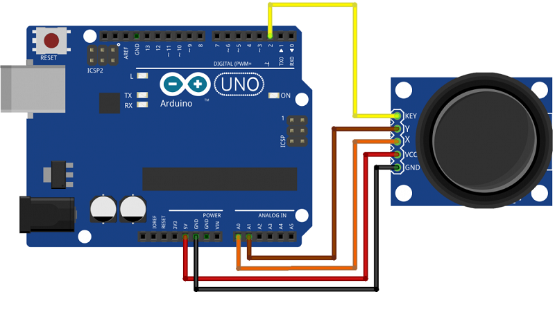
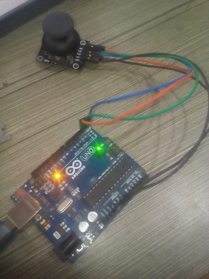
    - This week i connected Joystick as my input device and servo motor for my output devices on my self designed microcontroller board. This is related to my final project where whenever Joystick works it will turn servo motor and otherwise. I read about different input on Fab Academy , went through all the videos mentioned in the input devices.

    Getting started with Input devices

    My Assignment:-

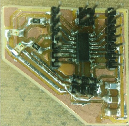
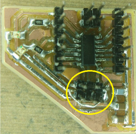
    In this week literly I dont know what to design in the board so I got help from my friend and the I edited his design and then i milled the board.

    I idea is to connect joystick to my design board.

    So I Redesigned this in eagle.

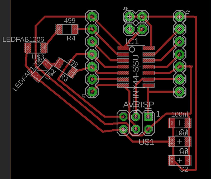
    You can download my design files here

    After Redesigning my files steps: -

    - I used vpanel software for milling my design. as explained in Electronics production.

    so I tried a lot to program but I cant because there is a problem in my board.

    u can see the pic below.

    The track has gone thats why it was not programming.

    so I Redesigned a new pcb for input of joystick.

    So my idea is to make a remote for my RC car so in that way i can complete my input devices assignement.

    I stated milling of my pcb..

    So this is the final

    After soldering.

    For more details of how I made design click here
  • code:-

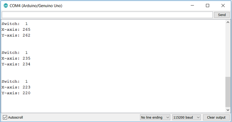
    // Arduino pin numbers
    const int SW_pin = 2; // digital pin connected to switch output
    const int X_pin = 0; // analog pin connected to X output
    const int Y_pin = 1; // analog pin connected to Y output
    
    void setup() {
      pinMode(SW_pin, INPUT);
      digitalWrite(SW_pin, HIGH);
      Serial.begin(115200);
    }
    
    void loop() {
      Serial.print("Switch:  ");
      Serial.print(digitalRead(SW_pin));
      Serial.print("\n");
      Serial.print("X-axis: ");
      Serial.print(analogRead(X_pin));
      Serial.print("\n");
      Serial.print("Y-axis: ");
      Serial.println(analogRead(Y_pin));
      Serial.print("\n\n");
      delay(500);
    }
    

    Before I test my Joystick in My board i wanted to test in Arduino

    We need 5 connections to the joystick.

    The connection are : Key, Y, X, Voltage and Ground.

    “Y and X” are Analog and “Key” is Digital. If you don’t need the switch then you can use only 4 pins.

    Analog joysticks are basically potentiometers so they return analog values.

    When the joystick is in the resting position or middle, it should return a value of about 512.

    The range of values go from 0 to 1024.

    so in this way I got the readings.

    My joystick is working.

    Now I should try in my board which I have designed.

    when I was trying to upload this code to attiny 44 it was an error in the code so i have to try it again.

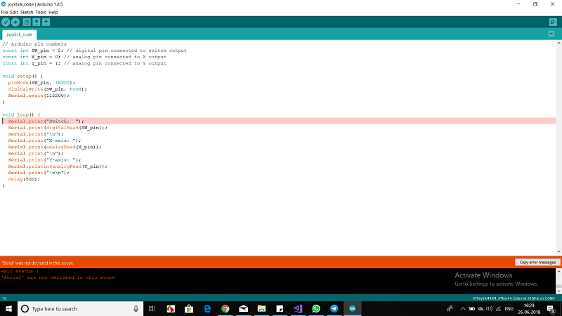
      D:\fab academy vimp\car\programimg\joystick_code\joystick_code.ino: In function 'void setup()':
    
    joystick_code:9: error: 'Serial' was not declared in this scope
    
       Serial.begin(115200);
    
       ^
    
    D:\fab academy vimp\car\programimg\joystick_code\joystick_code.ino: In function 'void loop()':
    
    joystick_code:13: error: 'Serial' was not declared in this scope
    
       Serial.print("Switch:  ");
    
       ^
    
    exit status 1
    'Serial' was not declared in this scope
    

    error given above.