Welcome to my week Final Project 2

PROJECT GARUDA

Basically my project is Electric Skateboard due to some problems I changed my project to Remote controlled car {GARUDA}

Introduction to GARUDA (RC cars)

Cars and Trucks have been the fastest growing category of radio control in the past decade and rightly so. They are fast, exciting, and something everyone of all ages can take part in at their own level.

R/C land vehicles fit into five main interest categories Off Road Buggies, On Road Cars, Monster Trucks, Stadium Race Trucks, and Motorcycles. All of these vehicles can be found powered by electric motors and more recently some of the vehicles have been offered in glow and gas powered versions.

REASON

I just wanted to make it because if u want to bye in market they sell for dobble price so i tought to make it in our lab.

And this idea given by my instrctor so thanks to him.

PROCESSES INVOLVED IN PROJECT.

  • LASER CUTTER
  • 3D PRINTER
  • NETWORKING
  • INTERFACING
  • VINYL PLOTTER
  • ELECTRONICS DESIGN
  • 3D Designing and 3D Printing

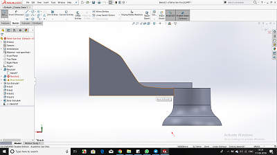
    3D designing of Jeep, Propeller, Remote. I have used Software Solidworks for the same. I tried making a complete product while designing. Designing has helped me bring my ideas to reality, being from nond esign background it was hard to learn new softwares , specially when every software has its own shortcuts and features.

    DESIGNING GARUDA (Jeep)

    I am not from a Design background but due to my interest in designing and bring in small elements to increase the functionality of my design, i was able to do this.
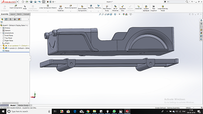
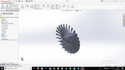
    Image Image Image

    3D printing of GARUDA(Jeep)

    3d printing seems to be an easy process but it relies alot on your design and settings you do while creating gcode to g file. While I used makerbot print, i was able to learn to control infill, support and support strength by the end of my project.

    Finnaly After a long wait of 48 hours I got all my parts in my hand and its feel good.

    Image Image Image Image

    Download .sld file

    Electronics

    Electronics in this project plays a major role, starting from making an 2 Attiny 44 board for my project 1 for Transmitter and the other for Reciever.

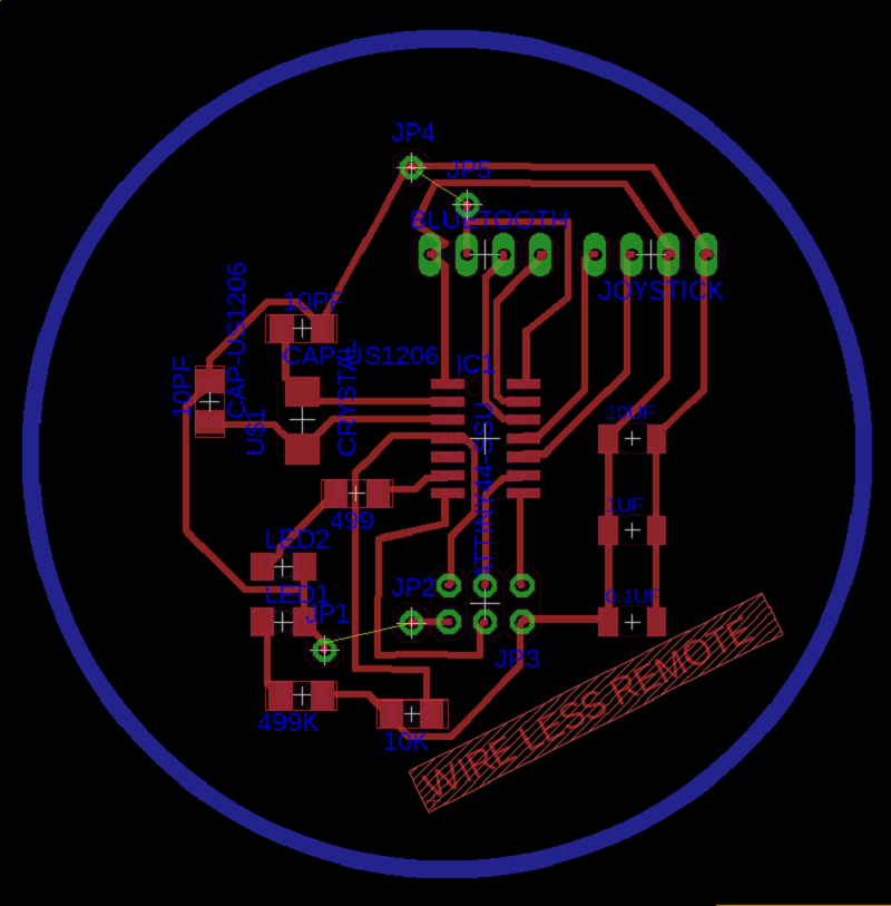
    Design for Transmitter

    So I have a Transmiting Bluetooth as a master and a joystick for moving my GARUDA (car) forward, right, left. there is no reverse in my car

    so I designed a pcb given below.........
    Image

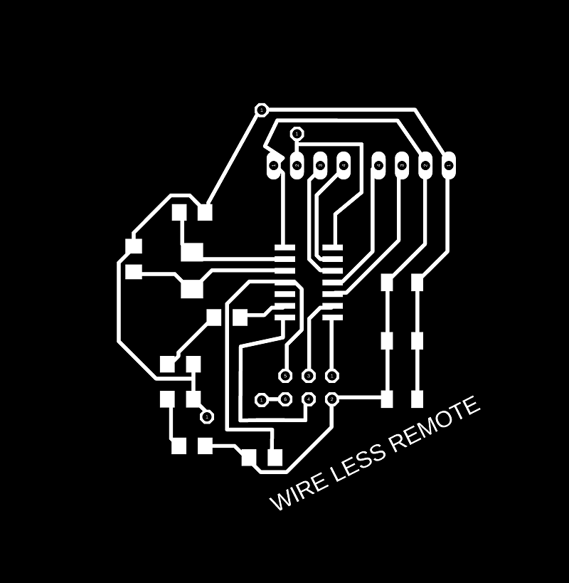
    I exported my file in .png so that I can mill my board..

    Transmitter traces Image Transmitter outline
    Image

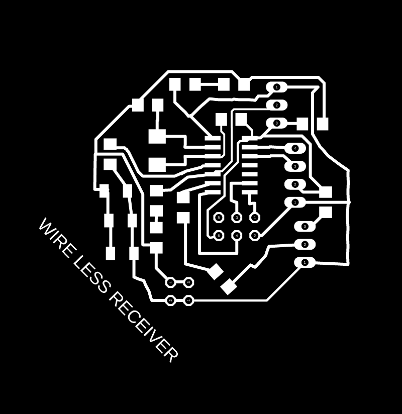
    Design for Reciever

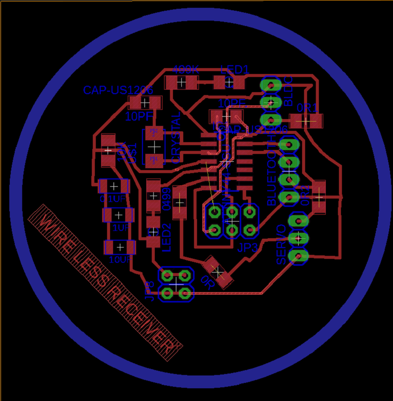
    So I have a Recieving Bluetooth as a slave and a esc for rotating my bldc motor and also a servo motor for direction of GARUDA
    Image

    Receiver traces Image Receiver outline

    Image

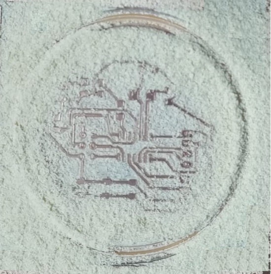
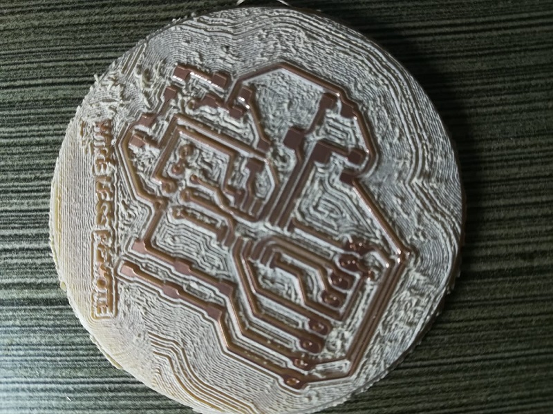
    Now Milling ............

    Transmitter
    Image

    Receiver

    Image

    So to know more information of milling process click here

    Download .png files

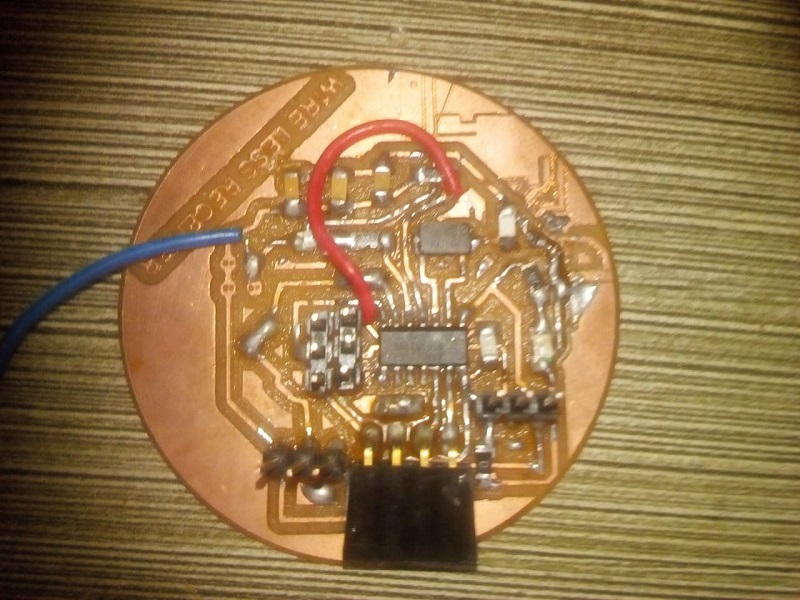
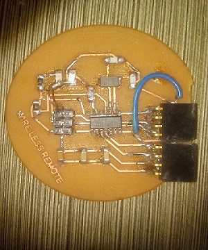
    Now soldering.........

    I brought all the components
    Image

    Image

    lets start Programing...

    so I complied blink code for testing.
     Transmitter blink code 
    		// the setup function runs once when you press reset or power the board
    void setup() {
      // initialize digital pin LED_BUILTIN as an output.
      pinMode(7, OUTPUT);
    }
    
    // the loop function runs over and over again forever
    void loop() {
      digitalWrite(7, HIGH);   // turn the LED on (HIGH is the voltage level)
      delay(100);                       // wait for a second
      digitalWrite(7, LOW);    // turn the LED off by making the voltage LOW
      delay(100);                       // wait for a second
    }


    - I used fab ISP to program my boards

    Image Code

     Reciever blink code 
    		// the setup function runs once when you press reset or power the board
    void setup() {
      // initialize digital pin LED_BUILTIN as an output.
      pinMode(2, OUTPUT);
    }
    
    // the loop function runs over and over again forever
    void loop() {
      digitalWrite(2, HIGH);   // turn the LED on (HIGH is the voltage level)
      delay(100);                       // wait for a second
      digitalWrite(2, LOW);    // turn the LED off by making the voltage LOW
      delay(100);                       // wait for a second
    }
    

    Image

    Before testing my the blue tooth code in my board I wanted to test in Arduino..

    Configuring the HC-05 Bluetooth Module – AT Commands

    In order to do that we need to switch to AT Command Mode and here’s how i did that. First I need connect the Bluetooth module to the Arduino as the circuit schematics. What we need to do additionally is to connect the “EN” pin of the Bluetooth module to 5 volts and also switch the TX and RX pins at the Arduino Board.

    . Image

    So the RX pin of the Arduino needs to be connected to the RX pin of the Bluetooth module, through the voltage divider, and the TX pin of the Arduino to the TX pin of the Bluetooth module. Now while holding the small button over the “EN” pin we need to power the module and that’s how we will enter the command mode. If the Bluetooth module led is flashing every 2 seconds that means that we have successfully entered in the AT command mode.

    After this we need to upload an empty sketch to the Arduino but don’t forget to disconnect the RX and TX lines while uploading. Then we need to run the Serial Monitor and there select “Both NL and CR”, as well as, “38400 baud” rate which is the default baud rate of the Bluetooth module. Now I am ready to send commands and their format is as following. Image

    All commands start with “AT”, followed by the “+” sign, then a and they end either with the “?” sign which returns the current value of the parameter or the “=” sign when we want to enter a new value for that parameter.

    Slave Configuration

    So for example, if we type just “AT” which is a test command we should get back the message “OK”. Then if we type “AT+UART?” we should get back the massage that shows the default baud rate which is 38400. Then if we type “AT+ROLE?” we will get back a massage “+ROLE=0” which means that the Bluetooth device is in slave mode. If we type “AT+ADDR?” we will get back the address of the Bluetooth module and it should looks something like this- 2011:2:315e9d.

    Image

    Now I need to write down this address as I need it when configuring the master device. Actually that’s all I need when configuring the slave device, to get its address, although I can change many different parameters like its name, baud rate, pairing password and so on, but I won’t do that for Now.......

    Master Configuration

    .

    Ok now let’s move on and configure the other Bluetooth module as a master device. First we will check the baud rate to make sure it’s the same 38400 as the slave device. Then by typing “AT+ROLE=1” we will set the Bluetooth module as a master device. After this using the “AT+CMODE=0” we will set the connect mode to “fixed address” and using the “AT+BIND=” command we will set the address of the slave device that we previously wrote down.

    Image

    Note here that when writing the address I have to use commas instead of colons. Also note that I could have skipped the previous step if we entered “1” instead of “0” at the “AT+CMODE” command, which makes the master to connect to any device in its transmission range but that’s less secure configuration.-- Here you can find a complete list of commands and parameters:

    HC-05 AT Commands List

    Nevertheless, that’s all we need for a basic configuration of the Bluetooth modules to work as a master and slave devices and now if we reconnect them in normal, data mode, and re-power the modules, in a matter of seconds the master will connect to the slave. Both modules will start flashing every 2 seconds indicating a successful connection.

    Communcation Between Two HC-05 Bluetooth Module Example

    Ok so now we are ready make the practical example for this tutorial. Here’s the circuit schematics. We will use a JOYSTICK, at the master, to control a servo motor at the slave. .

    Image

    Arduino Source Codes

    Description: So first I need to define the pins and some variables needed for the program. In the setup section, at the master, I set the LED pin as output and set it low right away, as well as, start the serial communication at 38400 baud rate. Similar, at the slave, Iset the button pin as input, define the servo to which pin is connected and start the serial communication with the same baud rate.

    In the loop section, in both code, with the Serial.available() function we will check whether there is available data in the serial port to be read and using the Serial. read() function we will read and store the data into the “state” variable. So if the master receive the character ‘1’ which is sent from the slave when the button state is high, or the button is pressed, the LED will be on. Else if the character is ‘0’ the LED will be off.

    As for the servo motor control, first at the master, we read the potentiometer value and map it into a suitable range for the servo from 0 to 255. This value is sent to the slave which use it to rotate the servo motor accordingly. That’s all we need and here’s the demonstration of the example.

    MASTER CODE

     
    #define ledPin 9
    
    int state = 0;
    int potValue = 0;
    
    void setup() {
      pinMode(ledPin, OUTPUT);
      digitalWrite(ledPin, LOW);
      Serial.begin(38400); // Default communication rate of the Bluetooth module
    }
    
    void loop() {
     if(Serial.available() > 0){ // Checks whether data is comming from the serial port
        state = Serial.read(); // Reads the data from the serial port
     }
     // Controlling the LED
     if (state == '1') {
      digitalWrite(ledPin, HIGH); // LED ON
      state = 0;
     }
     else if (state == '0') {
      digitalWrite(ledPin, LOW); // LED ON
      state = 0;
     }
     // Reading the potentiometer
     potValue = analogRead(A0);
     int potValueMapped = map(potValue, 0, 1023, 0, 255);
     Serial.write(potValueMapped); // Sends potValue to servo motor
     delay(10);
    }
    

    Download .ino file

    SLAVE CODE


    #include <Servo.h>
    #define button 8
    
    Servo myServo;
    int state = 20;
    int buttonState = 0;
    
    void setup() {
      pinMode(button, INPUT);
      myServo.attach(9);
      Serial.begin(38400); // Default communication rate of the Bluetooth module
    }
    
    void loop() {
     if(Serial.available() > 0){ // Checks whether data is comming from the serial port
        state = Serial.read(); // Reads the data from the serial port
     }
     // Controlling the servo motor
     myServo.write(state);
     delay(10);
     
     // Reading the button
     buttonState = digitalRead(button);
     if (buttonState == HIGH) {
       Serial.write('1'); // Sends '1' to the master to turn on LED
     }
     else {
       Serial.write('0');
     }  
    }

    Download .ino file

    lets edit the code for bldc motor to compile in my board

    MASTER CODE

     
     //this is master
    
    #include 
    
    SoftwareSerial BTSerial(10,11);
    
    long int analogPiny = 2;
    long int analogPinx = 3;  
    long int valy = 0;
    long int valx = 0;
    long int encoded = 0;
    String sencoded;
    int i,n;
    void setup() 
    {
     Serial.begin(38400);
      BTSerial.begin(38400);
      
    }
    
    void loop()
    {
      valy = analogRead(analogPiny);     // read the input pin
      valy = map(valy, 0, 1024, 110, 255);
      Serial.print("Y VALUE IS "); 
      Serial.println(valy); 
      valx = analogRead(analogPinx);     // read the input pin
      valx = map(valx, 0, 1024, 0, 180);
      Serial.print("X VALUE IS ");
      Serial.println(valx); 
      BTSerial.print("U*"); //A header
      BTSerial.print("A");  //a token to indicate the message payload
      BTSerial.println(valy);
      BTSerial.println("");  
    
      BTSerial.print("U*"); //A header
      BTSerial.print("B");  //a token to indicate the message payload
      BTSerial.print(valx);
      BTSerial.println("");  
     // delay(100);
    }
    

    Download .ino file

    SLAVE CODE


    #include 
    #include 
    
    Servo myservo;
    Servo esc;
    SoftwareSerial BTSerial(10, 11);
    long int var ;
    String data;
    String valys = "0", valxs = "0";
    int valy, valx;
    
    void setup() 
    {
      myservo.attach(8);
      BTSerial.begin(38400);
      Serial.begin(38400);
      esc.attach(5);
      esc.writeMicroseconds(1000);
      if (BTSerial.available() > 0)
      {
        data = BTSerial.readStringUntil('\n');
      }
      //Disregard the first reading
      data = "0";
    }
    
    
    void loop() 
    {
     if (BTSerial.available() > 0)
      { 
        data = BTSerial.readStringUntil('\n');  
      }
      String payload = ""; 
      if (data != "0")
      {
        int offset = data.indexOf("U*"); //This is the header (0x552A)
        if (offset >= 0)
        {
          payload = data.substring(offset + 3, data.indexOf('\n'));
          char value = data.charAt (offset + 2);
          switch (value)
          {
            case 'A':
              valys = payload;
              break;
            case 'B':
              valxs = payload;
              break;
          //Add more case as the project grow
          }
        }
      }
      //convert strings to float
      valy = valys.toInt();
      valy = map(valy, 0, 1024, 110, 255);
      valx = valxs.toInt();
      Serial.println(valx);
      Serial.println(valy);
      myservo.write(valx);
      esc.write(valy);
     
    }

    Download .ino file

    compliled my code in my boards......

    After compiling the code there are some erorrs..

    final video given below.......

    thanks for watching.

    "Click Here to go to Final Project 1 Documentation Page"