Week 8
Getting started with Computer Controlled Machining
This week's assignment was to create something big..... So I decided to make a wall hanging which would be looking like tree branches over the wall.

Getting Started
Firstly I started to look out for things which can be made with CNC router........ Then I came across this image and decided to make it over CNC ........ The first challenge in front was to make a 3D Image from a 2D Image........ So for that I started exploring over the internet and found a very good tutorial to convert 2D images to 3D using Inkscape and openScad...... For trial I made a android Logo in 3D ......
These were the steps I followed to create a 3D openScad file from a 2D file
1. Import the file in Inkscape
2. Select the Image
3. Then trace the bitmap, in this step play along with the setting to get the desired path

4. Now, delete the original file and work on the path which is traced .....
5. Now go to "Generate from paths" and make a open scad file

6. Save the file at a desired location

7. Now open the file in openScad and render it and then export it to STL file

Now since the practice session was over its time to work on actual picture ....... then following the same steps ...... the result was..


Machining
For machining one has to be familier with the machine toolpaths ....... To make machine tool path I used ASPIRE software ...... I imported STL file of my article .... and tried to make tool path using it .....

Then through SVG file final tool paths were created .....

The input format for the fabmodules was selected as PNG
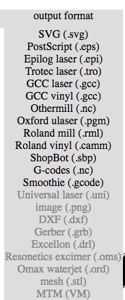
Then for the Output format SVG was selected
And then for the process Outline was selected

After the process the path was traced using calculate button and then it was saved
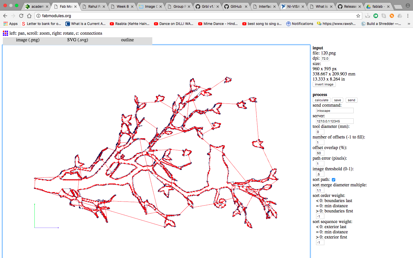
Now this SVG Image is furthur opened in Aspire and the tool paths were generated ....


Now that our files are ready to be machined...... Its time to have hands on with CNC
Working with CNC
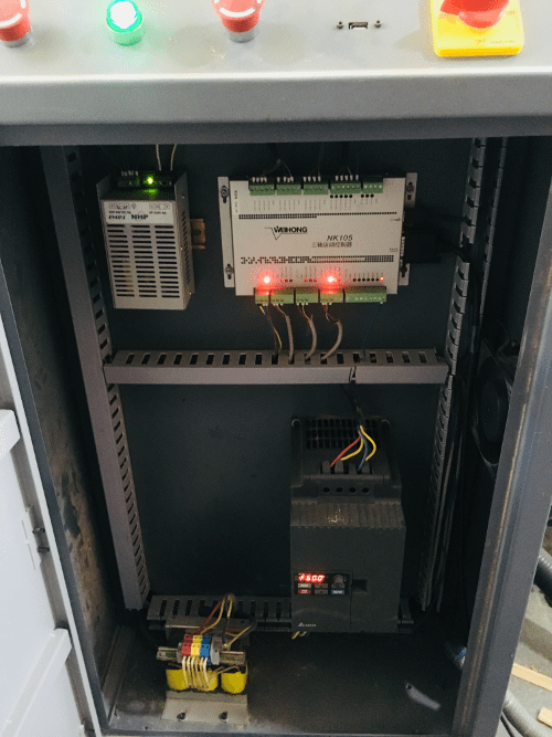
The CNC we had at our facility was an assembled one, Most of it is imported from china, the bed size is about 8X4 Feet
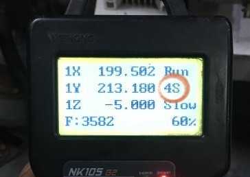
The feed rate and the spindle speed is controlled by Teach pendant in this machine unlike other ones, in which the feed and spindle speed is given in CAM Software
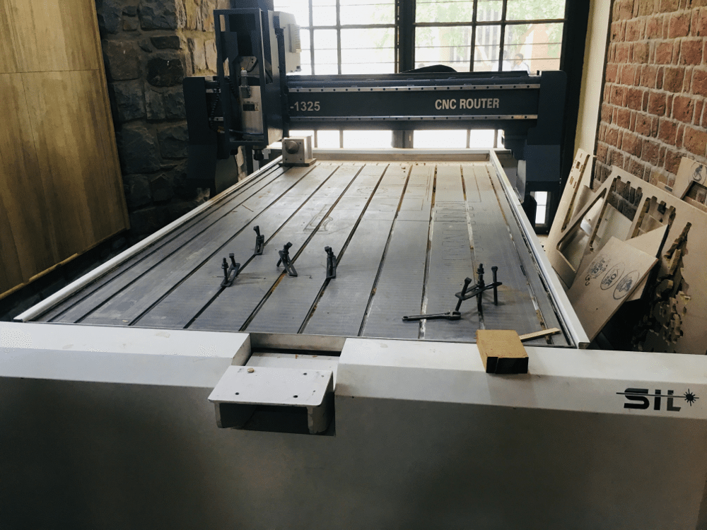
The controller
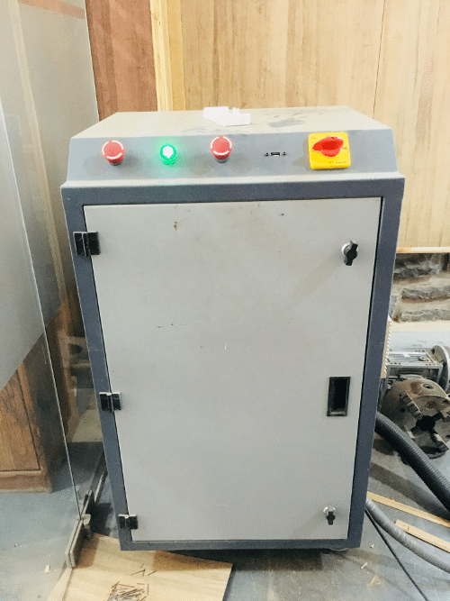
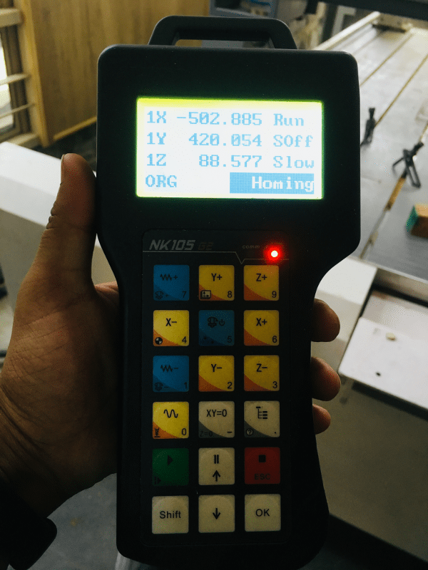
Teach Pendant
Initialization Tool
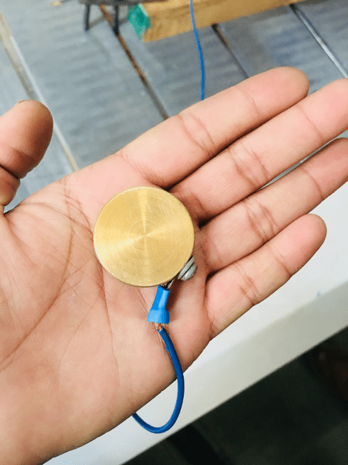
This tool is used to set the Z cordinate of the machine precisely, the X and Y home positions can be set via Teach pendant but the Z cordinate is set 11mm above the surface using this tool
Calibation in Action
Cutting Speed and Feed
Cutting speed is defined as the speed (usually in feet per minute) of a tool when it is cutting the work.
The cutting speed in this machine is mentioned in percentage 10% to 100%, My instructor has asked me not to go beyond 70% due to safety reasons.
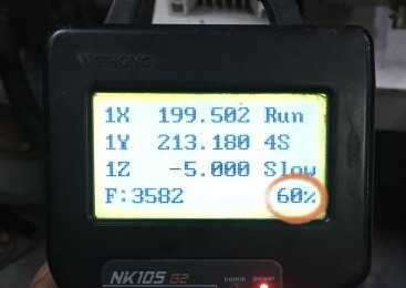
Feed rate is defined as tool’s distance travelled during one spindle revolution.
The spindle speeds in the machine is denoted by a number followed by S. They are 4S, 5S, 6S, 7S. 4S being the slowest and 7S the fastest.Tha maximum spindled speed at 100% is 3200RPM.
Testing Kerf and Runout
The tool isn't a perfect straight line, it has some degrees of freedom in the collet, and the collet might also not be straight. So, the reality is your tool wobbles a little bit, jiggles around as it goes around, and so runout is the actual diameter of what's cut. If what's cut is larger than the diameter of the tool, it is because of imperfections in how its held in the collet. And so, one of the things you have to test is the kerf and the runout. To test for runout, we cut holes at 6 different cut depths, and measured their inner diameters. The data is as follows:

Testing Speed & Feed
These were the observations.

Testing Tool Path
Conventional and climb machining was done in this test..... Both the tests seems to be ok
Conventional Machining : In conventional milling, the cutter rotates against the direction of the feed.
Few Facts about conventional Maching :
> Chip width starts from zero and increases which causes more heat to diffuse into the workpiece and produces work hardening.
> Tool rubs more at the beginning of the cut causing faster tool wear and decreases tool life
> Chips are carried upward by the tooth and fall in front of cutter creating a marred finish and re-cutting of chips
> Upwards forces created in horizontal milling tend to lift the workpiece, more intricate and expansive work holdings are needed to lessen the lift created
Climb Machining : In climb milling, the cutter rotates with the feed.
Few Facts about Climb Machining :
> Chip width starts from maximum and decreases so heat generated will more likely transfer to the chip
> Creates cleaner shear plane which causes the tool to rub less and increases tool life
> Chips are removed behind the cutter which reduces the chance of re-cutting
> Downwards forces in horizontal milling is created that helps hold the workpiece down, less complex work holdings are need when coupled with these forces
When to Choose Conventional or Climb Milling
Climb milling is generally the best way to machine parts today since it reduces the load from the cutting edge, leaves a better surface finish, and improves tool life. During conventional milling, the cutter tends to dig into the workpiece and may cause the part to be cut out of tolerance. Even though climb milling is the preferred way to machine parts, there are times when conventional milling is the recommended choice. Backlash, which is typically found in older and manual machines, is a huge concern with climb milling. If the machine does not counteract backlash, conventional milling should be implemented. Conventional milling is also suggested for use on casting or forgings or when the part is case hardened since the cut begins under the surface of the material.

CNC in Action
Final Outcome

Download all Files Download SVG/Image/CNC File