Week 15
Getting started with Mechanical Design & Machine Design
This weeks assignment was to make a machine which involes actuation, automation and mechanism ........
After a lots of brainstorming with the team ........ after bypassing lots of ideas ........ which were not feasible in this time window ...... we decided to make a POLOGRAPH........ well I was a noob in machine design ..... but one of our group member was from mechanical design with a sound practical knowledge ...... so it was a bit easy for me to digest POLOGRAPH...... well from my understanding point of veiw.... what I understood was its a 2D plotter but vertical ........ well it sounded a bit wierd to me at first ..... but after going through lot of internet pages about polographs ....... I was suprized to see people doing wonders with this simple machine ..... then I started working on the same machine ...... I studied what all people have done and how they have done ......
So after all this we started to make somethings on a page ....... Abhinav from our group ( The mechanical guy ), took the responsibilty to make a sketch of the machine ...... here I am sharing his Sketch.....
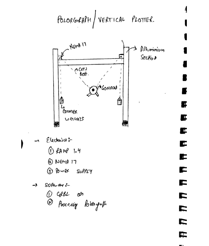
Well...... this is not just a sketch ...... it was the outcome of 2 days of brain storming.....
After this we decided to divide the roles among us so that the machine can be made within the time window .......
Division of Roles
Well .... this was a crucial step to ensure that the machine is made within time and operational ........ So we decided to divide the roles as per everybody's comfort and experience ....
So here's how we divided the roles :
1. ABHINAV GARG ----------> Mechanical Structure and design
2. RAHUL GAUTAM ----------> Electronics
3. ADITYA ----------> Mechanical Structure and design
4. ASHISH SAWHNEY ----------> Jack of all.... but Majorly Documentation
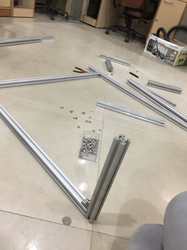
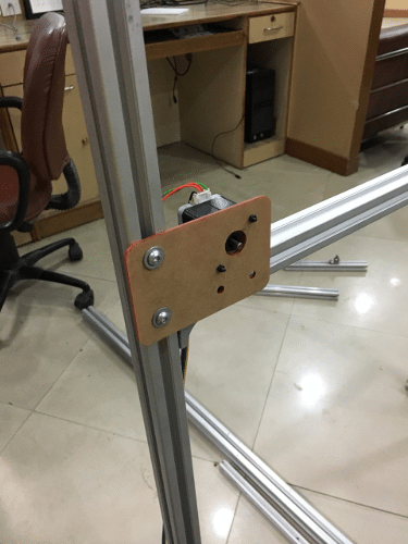
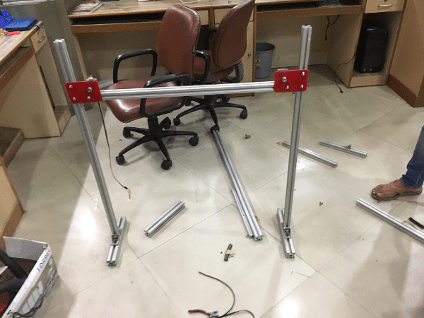
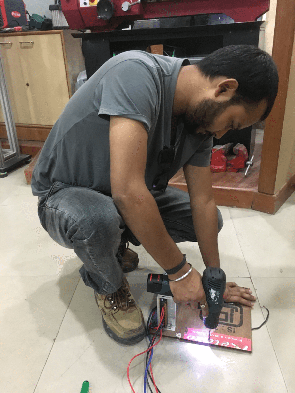
After the division of roles our group started working on the mechanical design first ....... for the raw materials ...... we used what was available in the lab ..... we used some older projects..... which we dismanteled ( ohh.... we are heartless people ) and then used them to make the sturcture of the machine ..... Apart from than we made some mountings for the motor using LASER Cutter........
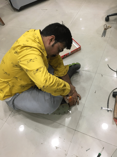
Here are few snaps of the machine assembling
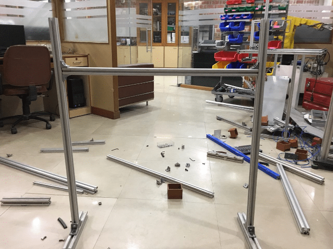
At the end of this week we have a working mechanical structure ..... Now I am looking forward to understand its firmaware and work on the electronics which would be needed to make this machine work....
Getting Started with Machine Design
This weeks assignment was to automate the movement of motor and achieve desired positioning through mechanical system ...... i.e we have to make it work ......
So my role in this weeks assignment was to work on the firmware and electronics of the system ...... So I started with understanding the working of stepper motors ....... then I moved ahead towards its drivers ...... then I learnt about interfacing it with arduino ....... then finally we decided to use RAMPS board......
To understand the working of stepper motor one can refer this video ....
After going through some pages over the internet ..... I got to know .... there are many ways to actuate a stepper motor ..... it can be actuated using ULN 2003a(Darlington pairs) IC or through L293D Motor driver IC or using A4988 Motor Driver ...... A lot of people have faced heating problems with ULN2003 and L293D..... So I decided to move ahead with A4988 Driver IC as its not that expensive and was available in Lab ..... So here's a video I refered for understanding and using A4988 driver IC with Arduino
For more detailed understanding
1. 4 connections to the stepper motor, marked 1A, 1B and 2A, 2B. Connect the first coil to 1A and 1B and the second coil to 2A and 2B.
2. Logic Power and GND, Connect this to the GND and +5V of the Arduino
3. Dir sets the direction the stepper will move. I connected this to Pin 4 on the Arduino
4. Step will make the stepper step each time this pin goes form Low to High. I connected this to Pin 5 on the Arduino
5. Enable. When this pin is pulled low the board is enabled and the motor energised. When set high the board is disabled and the motor is de-energised. I connected this to Pin 6 on the Arduino
6. Sleep and Reset control the board, either sending it to sleep or resetting it. To use the board I tied these together which allows the board to run normally
7. Motor Power and GND. This needs to be a high voltage/current supply to run the motor.
Note : Warning: Connecting or disconnecting a stepper motor while the driver is powered can destroy the driver. (More generally, rewiring anything while it is powered is asking for trouble.)
To prevent damage to the driver chip, it uses circuitry to limit the maximum current that can be used. This is set via the adjustable resistor on the board, in co-operation with some of the other components, the sense resistors (S1 and S2) and the resistor (R1). As different drivers may have different components (especially generic Chinese imports) its best to check these values before continuing.
For my stepsticks S1 and S2 are marked 'R10' and R1 is marked '303' (in very small writing !). These correspond to 0.1Ohm for S1 and S2 and 30kOhm for R1. The trimpot should be 10kOhm substituting those values, gives
VREF max = (TrimpotMaxR/(TrimpotMaXR+R1)) x VDD = (10,000 / (10,000 + 30,000)) * 5 = 1.25V
ITripMAX (effectively max motor current) = VREF / ( 8 x Sense_resistor) = 1.25 / ( 8 * 0.1 ) = 1.5625A
As my stepper motors are 2.0A, I can't get maximum current from this driver, however,if I drive them at 70% (2.0A x 70% = 1.4A) I want to a VREF of 1.4A x 0.8 = 1.12V, plus driving them at 70% will reduce the temperature of the stepper.
I start with the trim pot turned anti-clockwise, and measure the voltage with my multimeter between the logic Gnd pin and the centre of the trimpot itself, slowly turning it up until I get just under 1.12V
Once that is done, you can connect the Motor power supply (12V). Hopefully your motor will start running !
Now since I was familier with the stepper motor operation ....... I decided to move ahead with RAMPS Board ...... I got its referance via Neils Lecture and also by my local instructor as he was familier with the board and has used it earlier in his projects .....
RAMPS Board
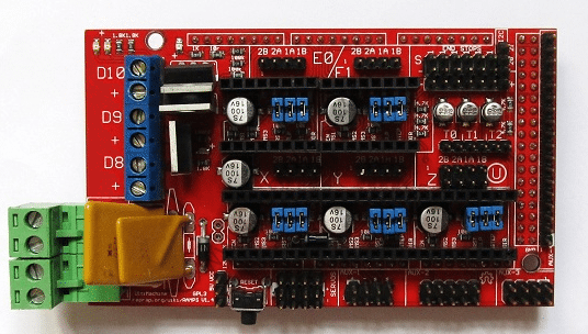
Ramps is a driver board designed for 3D printer, based on platform (firmware) Repap. It not only drivers four steppers so you can design many types of machines based on it, like CNC, and as a mature platform specially for 3D printer, it also driver extruder, fans, temperature sensors, SD card, etc.
It is designed to fit the entire electronics needed for a RepRap in one small package for low cost. RAMPS interfaces an Arduino Mega with its powerful platform and has plenty room for expansion. The modular design includes plug in stepper drivers and extruder control electronics on an Arduino Mega/Sainsmart MEGA shield for easy service, part replacement, upgrade-ability and expansion. Additionally, a number of Arduino expansion boards can be added to the system as long as the main RAMPS board is kept to the top of the stack.
Here is a Video you can refer to understand RAMPS Board
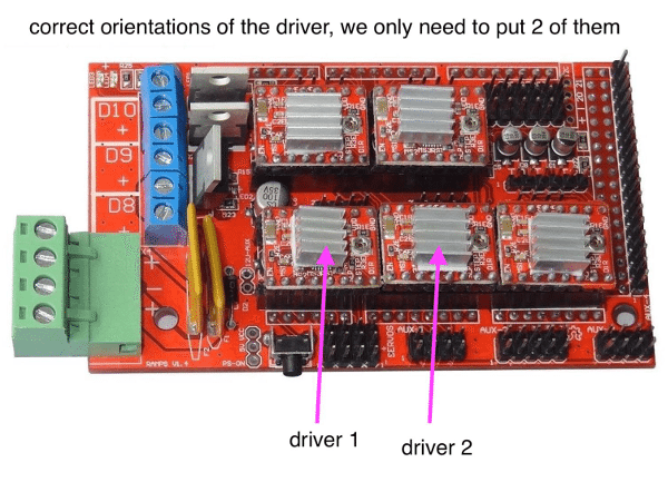
well ... what I understood from RAMPS board is ....... its a complete PCB Setup for multiple motors and it can be mounted on Arduino MEGA ...... or we can say .... its a shield for arduino MEGA with 5 stepper motor driver space and much more .... ( which can b required by a 3D printer ) ....... For Our machine we were going to use X and Y motor outputs from the board
Since I was familier with stepper motor actuation .... I straight away moved ahead towards the firmware ......
Firmware
I started with couple of videos ......... and downloaded the firmware ......
I downloaded the firmware from the link in the description but I was unable to compile the code ...... it was showing some errors ..... and Since we were out of time we decided to move ahead and find some another firmware ....
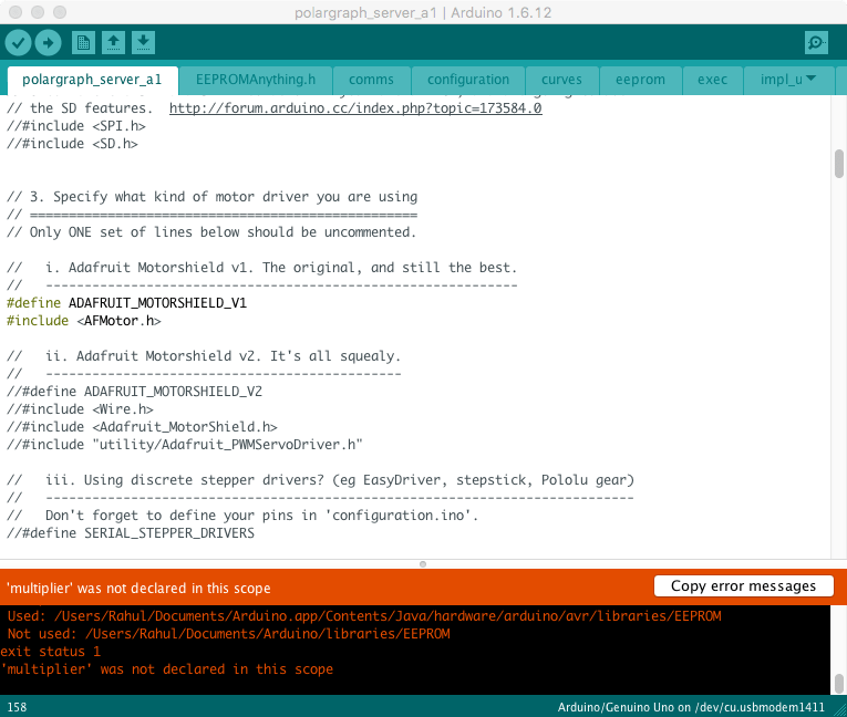
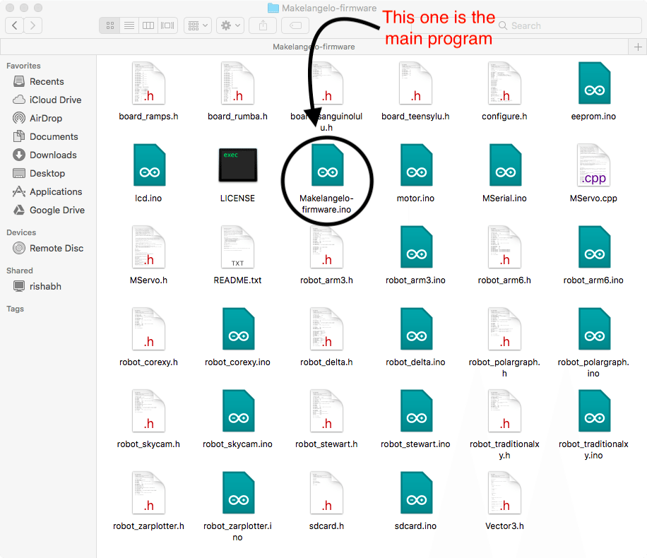
Even after declaring this in the main program there is one error or the other ..... So, I decided to move ahead with some another firmware .... I came across with MAKEANGELO Platform it was quite modular and was easy to use ...... It has all the logic and calculation required to run the machine smoothly and precisely....... aprt from that ... it had an interface for controlling the Polograph......
These are the instructions which have to be followed before uploading the firmware
- Make sure the parent folder is called Makelangelo-firmware.
- Open Makelangelo-firmware/Makelangelo-firmware.ino in arduino
- In Makelangelo-firmware/configure.h make sure BOARD_TYPE and MACHINE_STYLE are set for your board and machine style
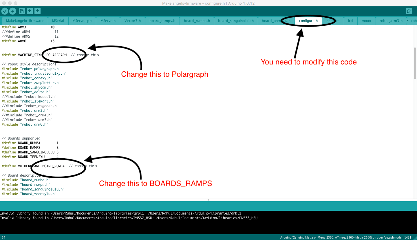
- For Makelangelo 3 or Makelangelo 5, choose POLARGRAPH
- For Makelangelo robots, in Makelangelo-firmware/polargraph.h, set for Makelangelo 3 #define MACHINE_HARDWARE_VERSION 3 for Makelangelo 5 #define MACHINE_HARDWARE_VERSION 5
- Tools > board > set type for your flavor of arduino
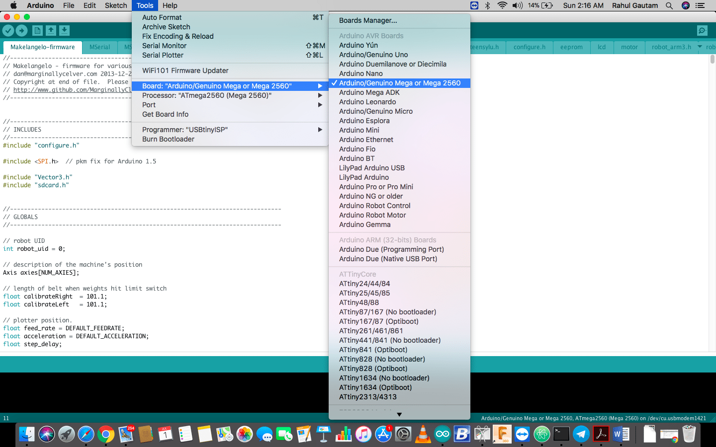
- Tools > port > set the connection for your arduino
- Upload
After uploading the firmware ..... we wired up the motors ..... we connected the system with the interface, Customized it according to the machine design and tested it with some basic commands like ..... home position ..... 10 steps+ or 10 steps- , the motors were connected on the X and the Y axis of the RAMPS Board ......
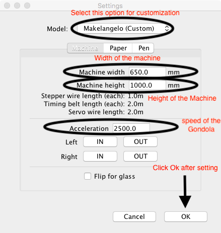
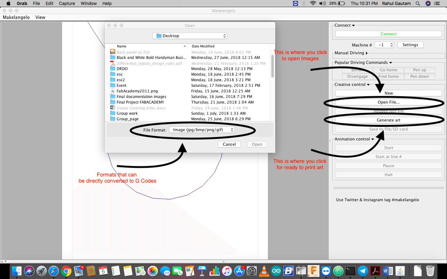
Now that we have motors connected with the RAMPs Board over X and Y, I moved ahead with Exploring the Interface, All we need to do now was to customize the machine according to the dimensions..... Here I am Sharing how to customize the settings...
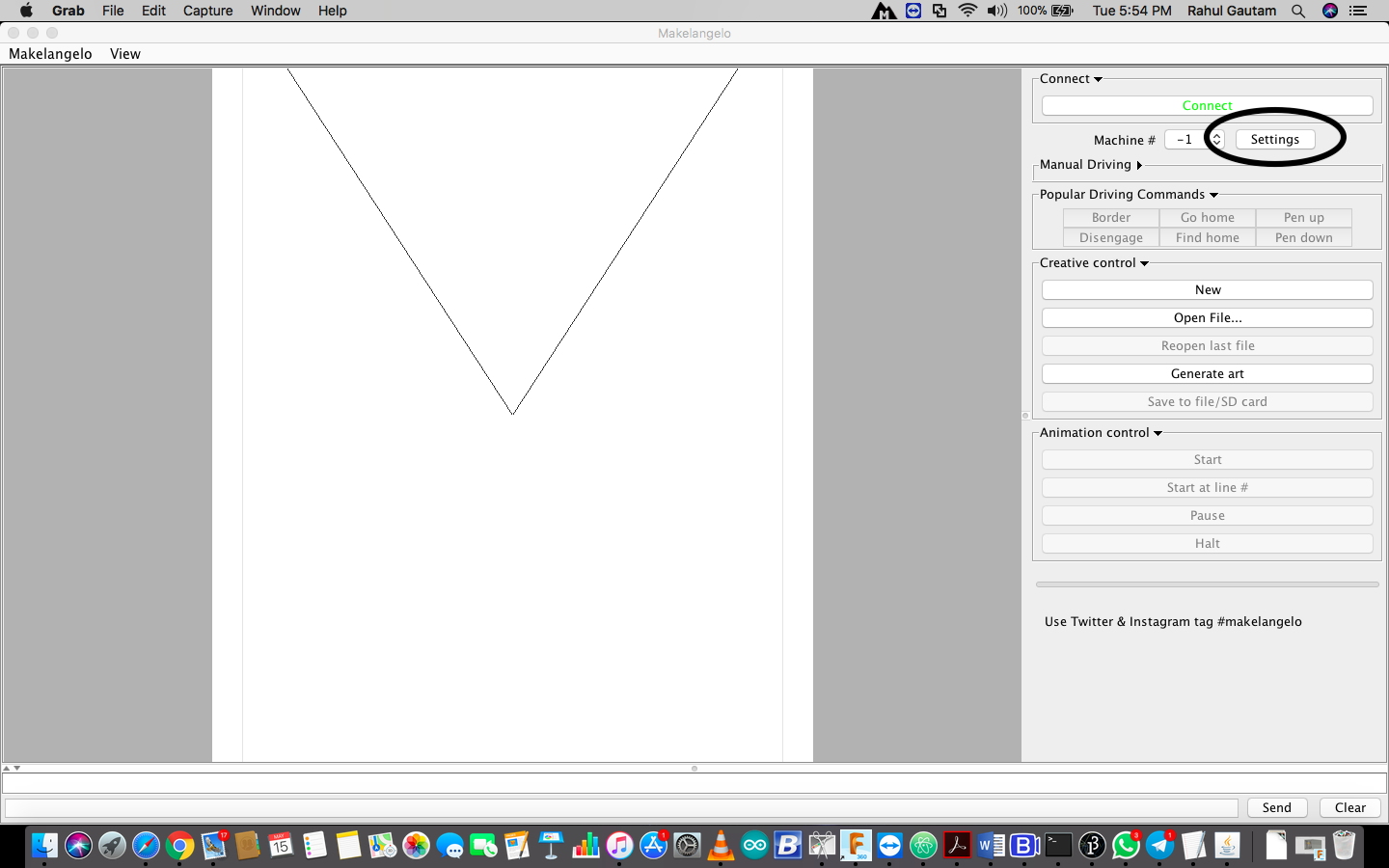
This is the main interface, and for customizing the machine we need to click on settings
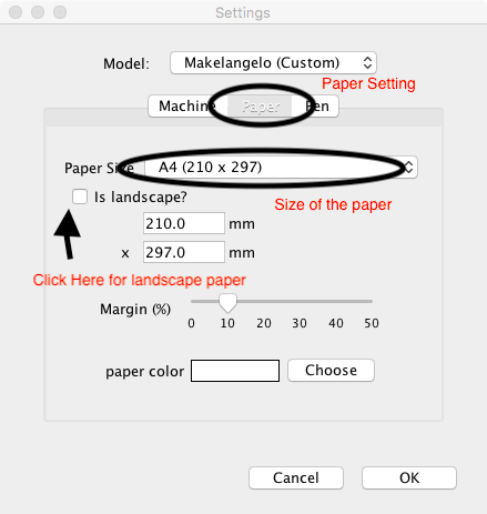
Now here is the paper setting you have to make for A4 Sheet
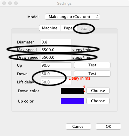
Now that Machine and Paper settings are done we need to move ahead with the pen Settings
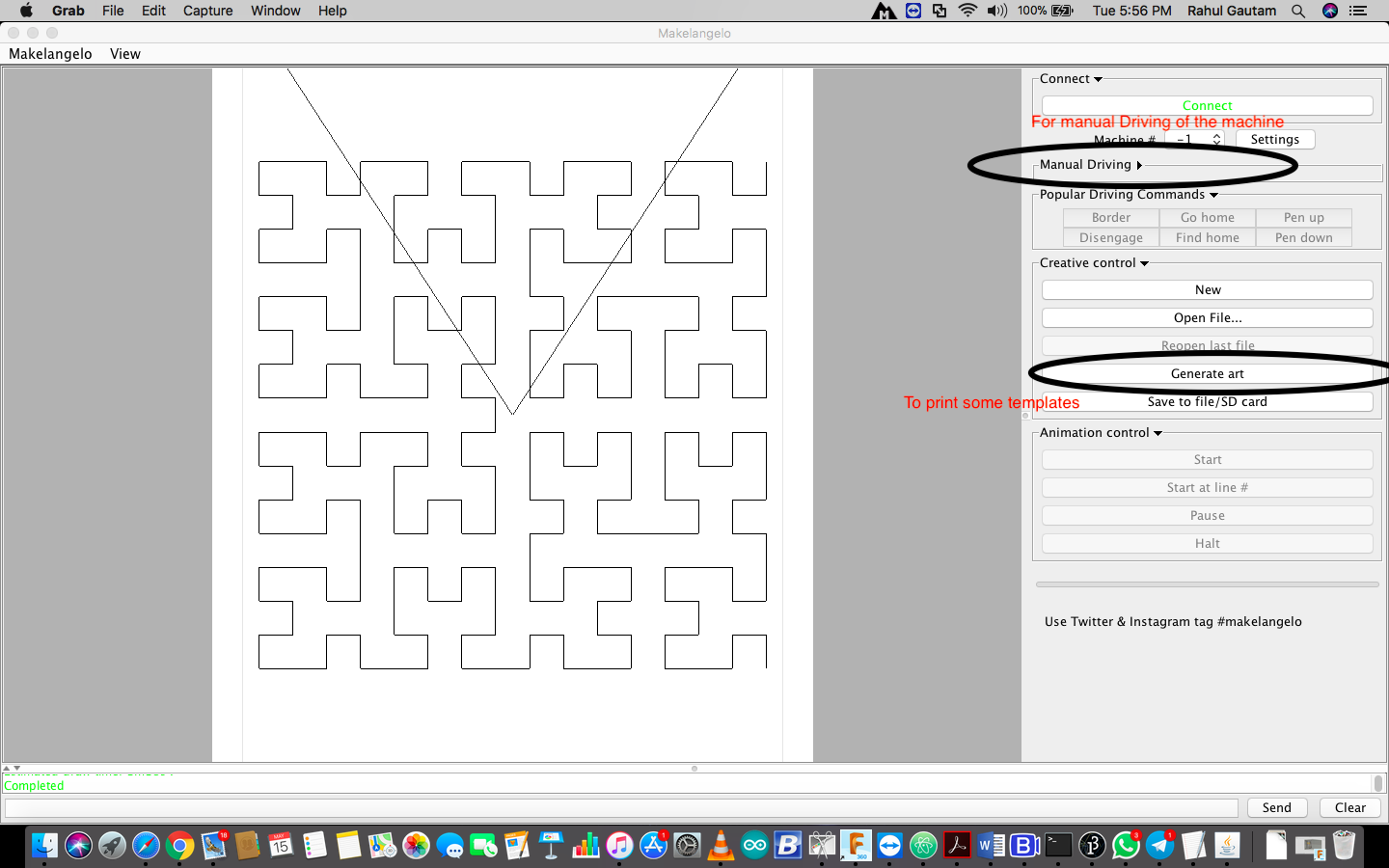
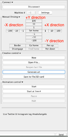
To print some templates you click on the generate art......but before that we need to test whether the machine is working or not. For this we need to test the machine manually. Go to the Manual Driving (as marked above) then you can test the motion of the gondola.
Note : If the motion is in opposite direction to the intended motion then we need to reverse the motor connections over the RAMPS board. Also one should keep an eye over the motor drivers, whether they are heated or not, if they heat alot ......... There is some problem, Switch off the system and check the connections.....
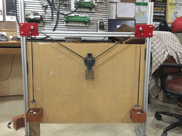
Fortunately over motors were working perfectly fine, Now we started with Cleaning up the wires, What we did was we placed the wires in between the profile and taped it, It looked neat and clean.
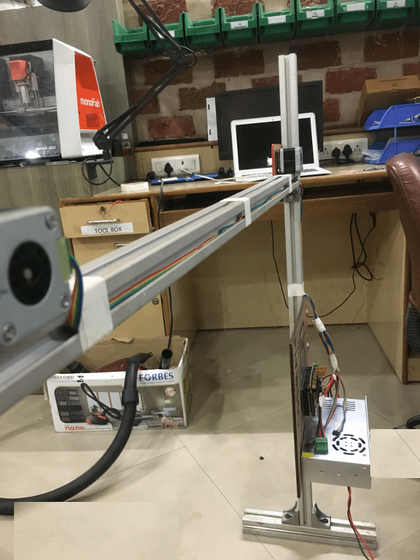
For placing the Arduino and RAMPS Board along with the power supply we took a plyboard piece and screwed everything on that and then screwed that plyboard on profile.
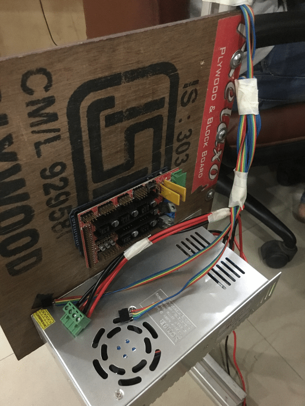
The power supply we used was 24V 15 amps from an old self assembled 3D printer, Its features are :
Brand                             : Omron
Type of Product                   : Switch Mode Power Supply
Output Voltage(V DC)              : 24 VDC
Output Current(Amp.)              : 14.6 A
Dielectric Strength	          : 1.5 kVAC for 1 minute
Vibration Resistance	          : 10 to 55 Hz, 0.26-mm single amplitude for 2 h each in X, Y, Z direction
Mounting Type	                  : Din Rail Mounting 'CD'
Efficiency	                  : 0.8
Ripple and Noise	          : 100 mV
Operating Temperature             : -10?C to 60?C
Size (mm)                         : 46 x 97 x 105 mm
Weight (Kg)                       : 0.36 Kg
Input Frequency                   : 47 to 64 Hz
Input Voltage (VAC)               : 200-240 V AC
Power Rating	                  : 350 W
Model No                          : S8JC-Z350
Features	                  : Material cost reduction, It is safe to use. It is with overload protection 105% Of rated load current and
                                    overvoltage protection, Voltage Drop, Intermittent, Automatic Reset. Green Colour Output Indicator.
G code Generation
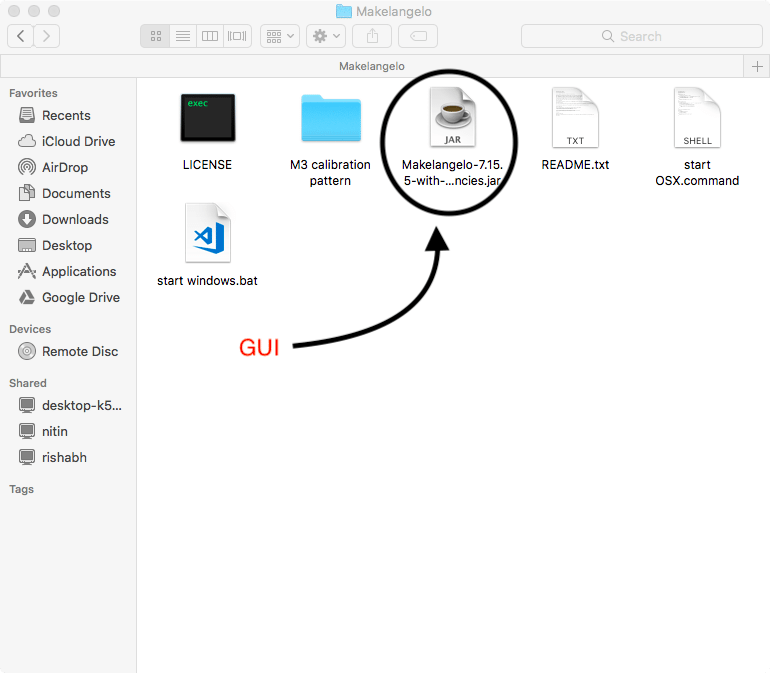
Makelengelo has its own GUI this is a execuable jar file in the extracted folder, we need to have the latest java installed in our computer to connect our pc to the board, an interesting thing about Makelengelo is that it can convert image files into gcode on its own, thus you dont require to download any plugins for it, you can just import an image the software will convert it into gcode. We can also import gcode if we have a better gcode converter.GUI There are also ready to print images in the GUI in the generate art section.
Here is the working video of the machine .......
The link for the Gandola (Pen holder) is as LINK
The link for the Firmware and Inteface is as LINK
Conclusion
> I justified my role in this project and to summarize :
> I used Arduino MEGA + Ramps + A4988 + NEMA 17 motors x 2 + Omron Power supply and interfaced them all.
> Then to test the system I dumped Makeangelo Firmware on Arduino MEGA without modifing anything, as in Makeangelo it can be done with the user Interface.
> Then through User interface I feeded the parameters according to the design and customized the software according to the design.
> Then after feeding all the paramters, I cleaned up the wiring and tested the system with a test design template ("Generate Art") which was shown in the Video
Furthur Scopes
> Each line of the Firmware can be studied and improved.
> Better calculations of the machine dimensions can be done in order to improve the resolution of the machine.
> PCB can be designed with only 2 motor drivers as RAMPS board must be feeling under utlized in this machine.
> Counter weights can be accurately calculated to make sure the motion of Gondola is correct.
> The gondola is not stable, Work can be done to improve the pen holding mechanism, it was shivering while drawing