Week 10
Getting started with Moulding and casting
This weeks assignment was to design a 3D mould, Machine it and cast parts from it.
I was a bit confused what to make ...... It was a completely new thing for me..... After a lot of ideas... I decided to make a Chess Piece..... Now again I was a bit worried how would I make a chess piece on 3D designing software as it would have a lot of curves and everything ....... I had a discussion with my local instructor and learnt about the work flow which I would be following to create mould and cast objects.....
These are the steps :
1. Take a image of the chess piece and trace it on 3D designing software.
2. Make mould of the object.
3. Export STL file to a CAM software ( Modella player ).
4. Make tool path and export G codes to the machine.
5. Make a Soft negetive of the object.
6. Make the final product.
Designing the Mould on Fusion 360
For desiging the mould I took an image of the chess piece I wanted to make and then imported the same image in fusion 360 as canvas...... now I traced half of the object ......
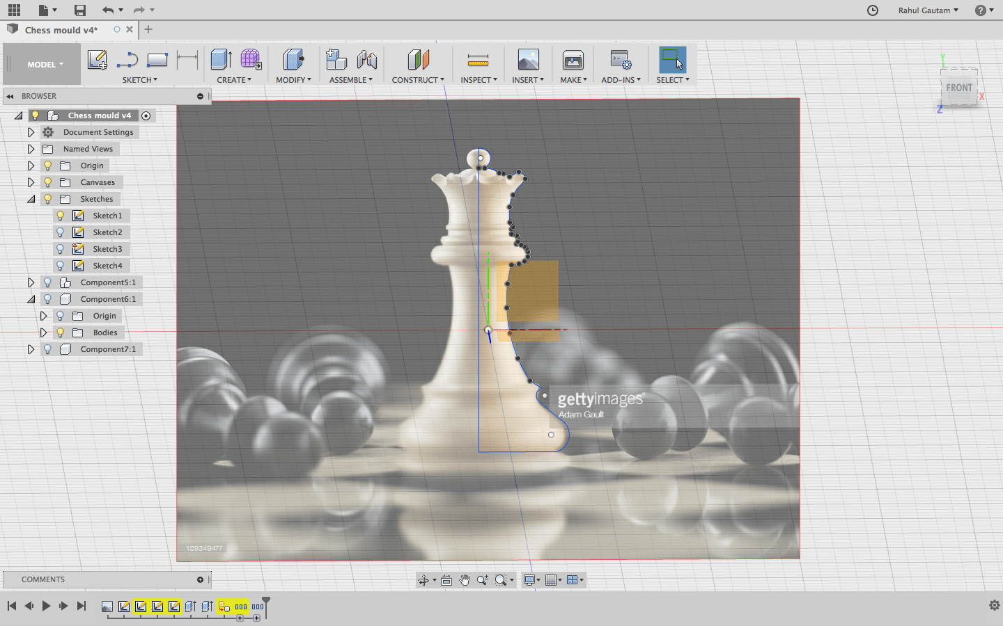
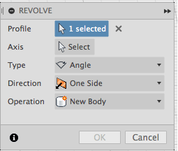
Now using the Sketch and Revolve option I made half of the chess piece ...... I revolved the sketch by 180..... As I was supposed to make the final product in 2 pieces.......
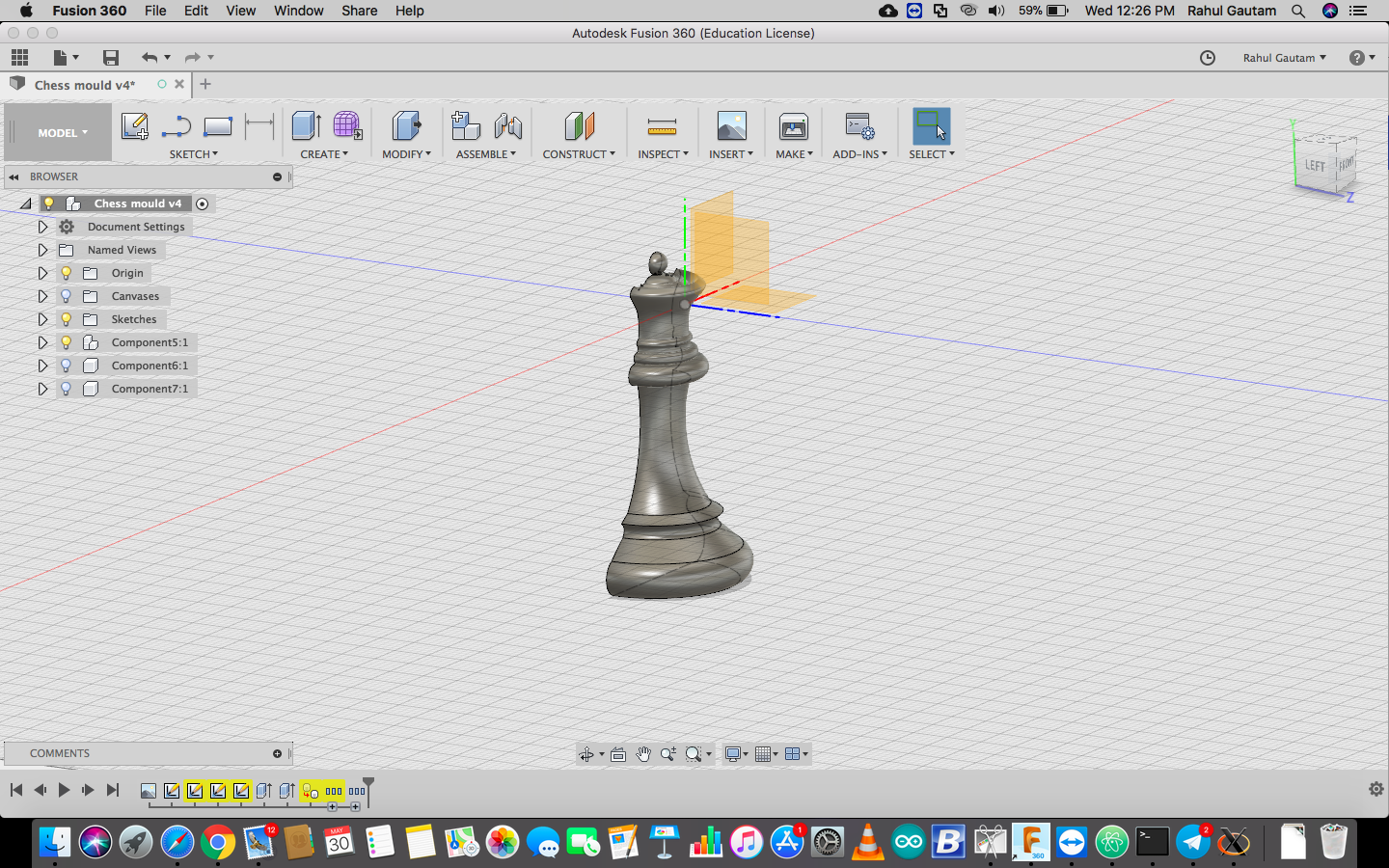
Here is the final result after the revolve operation
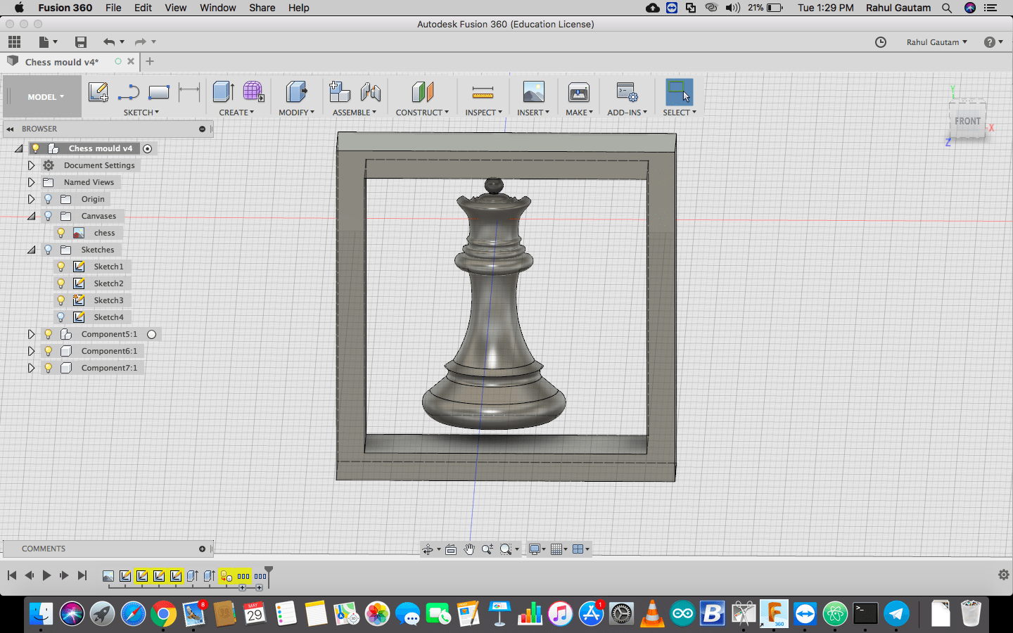
Now after the work piece is ready we need to make a boundary across the piece as it would be holding the moulding material...... as a container ..... this was a simple operation to do .... just make a rectangle across the piece and extrude....
Now that my model is ready ..... I exported it to STL file.... which would be furthur used to make tool path on Modela Player
Download Design FilesMaking tool path
Now for making tool path I was supposed to use Modela Player....... this was a new software for me ...... but one of my friend Aditya taught me how to make tool paths...... It was super easy .... all I need to do was just follow steps and enter the parameters as they were ...... Parameters included ....... material width .... type of material.... tool diameter etc etc.
Follow these steps to create the tool path :
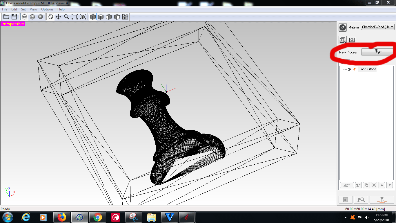
Import STL file in Modela player and select a new process
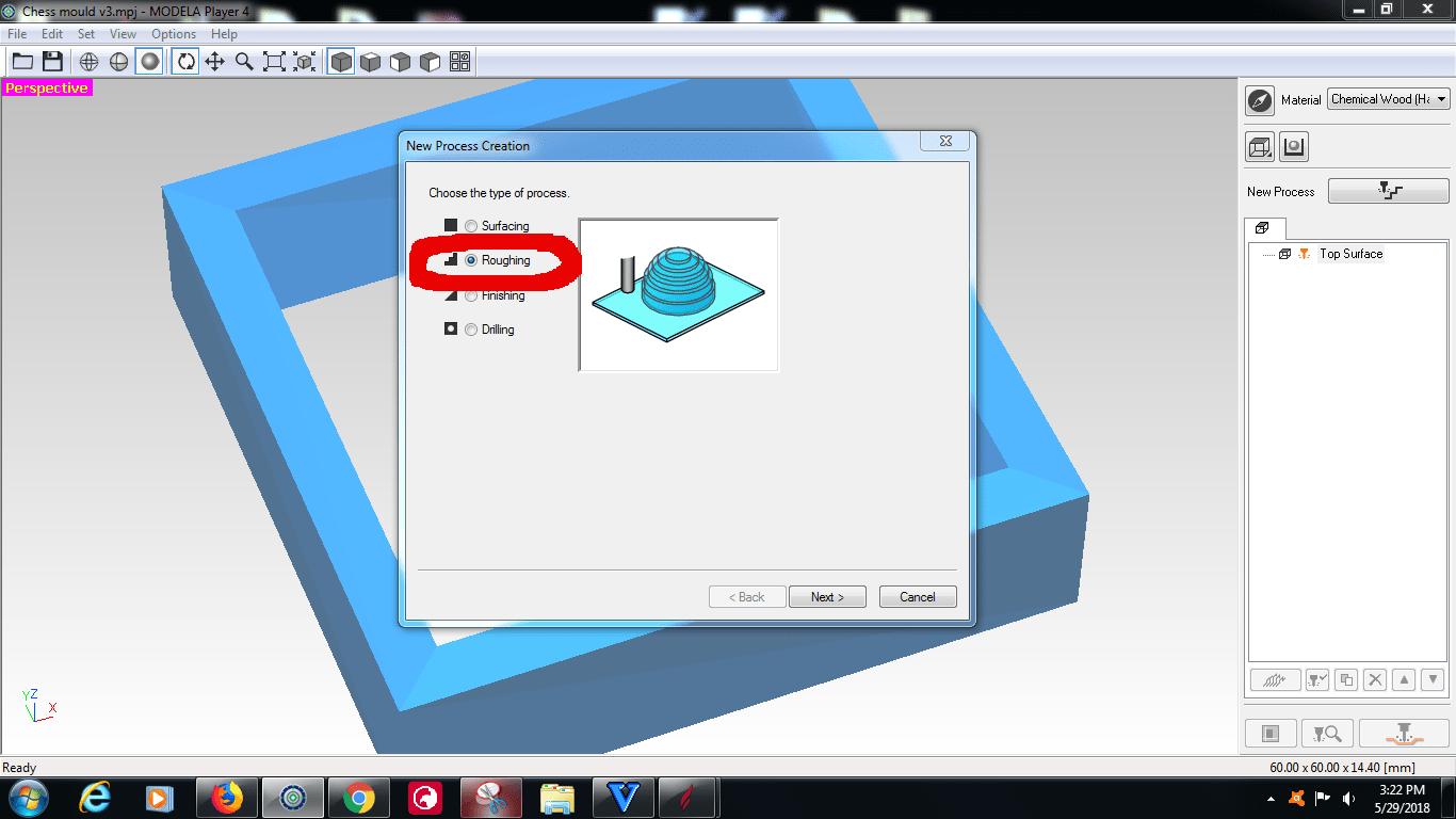
Now Note that the whole process would be done in 2 tool operations ...... 1st one would be roughing and the 2nd one would be finishing .....
So firstly we'll move ahead with creating tool path for Roughing
Now select Roughing operation and from there onwards follow the instructions and enter parameters
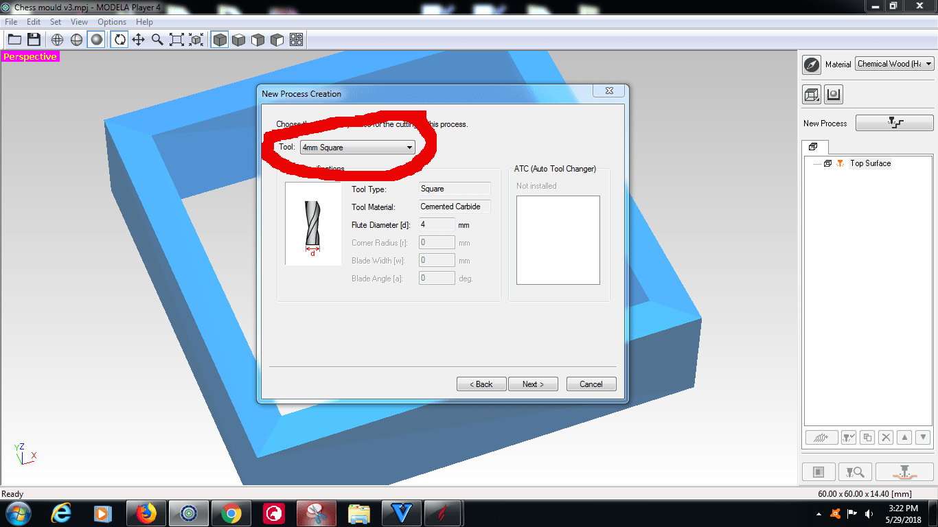
Here we need to enter the diameter of the tool we are using .... in my case it was a 4mm tool.
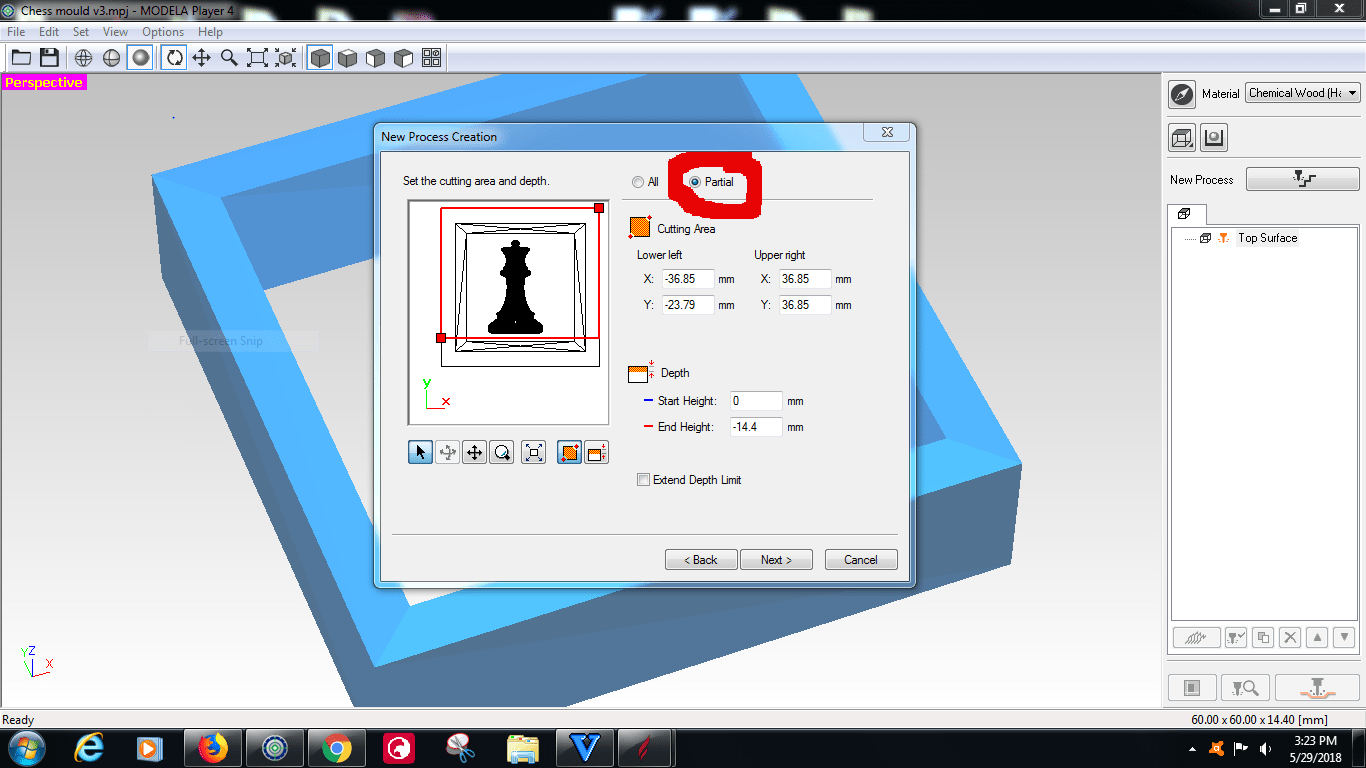
Now in this window we need to decide wether we need to cut the whole design or we can go ahead with partial selection ......... In my case to avoid material wastage I choose partial cutting area and manually selected the cutting area
Now in this step we need to select how the tool would move ..... we can leave it as it is
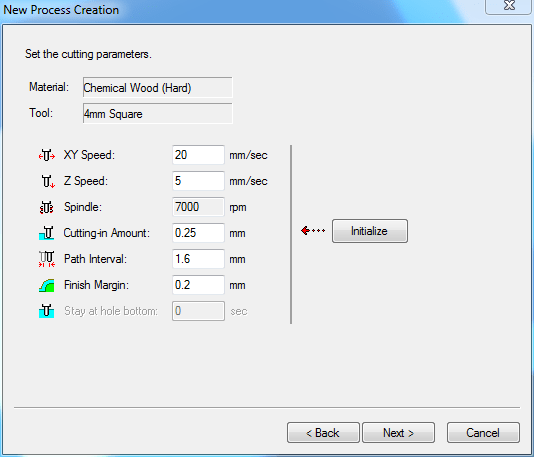
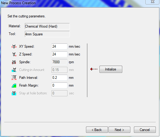
Now in this step we need to initialize the machine ....... we need to fill in the parameters .....
XY Speed : this is the speed by which the spindle would move in XY Plane, we can leave it at default value
Z speed : Its the speed by which the spindle would go up and down, we can leave it as it at default value
Spindle : RPM of spindle
Cutting in amount : How much the tool would cut in one pass
Path Interval : Distance between two contour lines, the more closer it is ...... the more fine the piece
Finish Margin : How much material it would leave befor touching the boundry of the cutting area
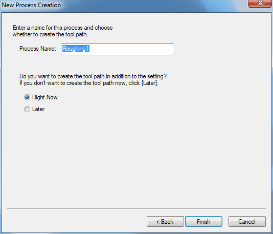
Here you can change the name of the process and decide when to create the tool path .... immediately or later
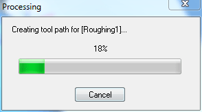
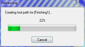
After you click on the finish button.... you'll see the following window, which means the tool path is being created...
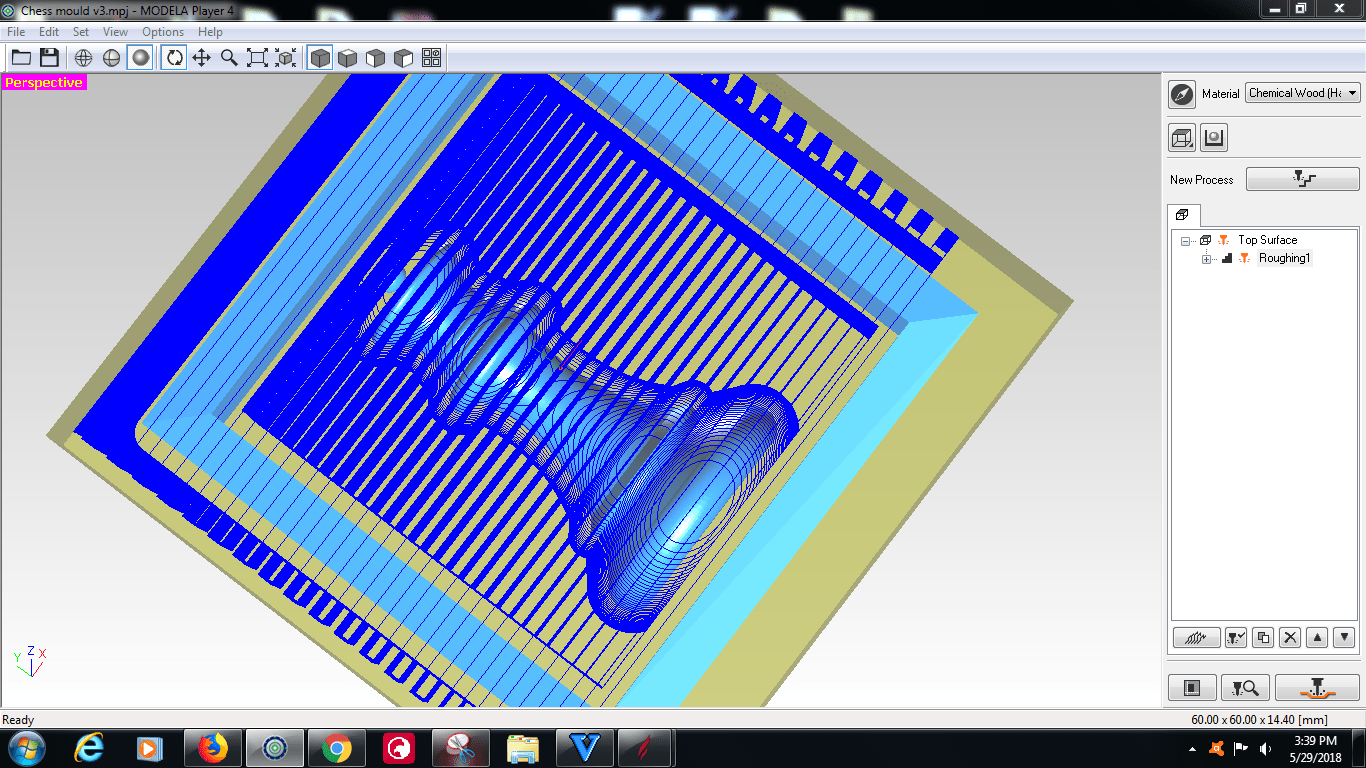
Now if we do this operation only .... the mould would be close to the actual design but it wont be actual ....... it wont be having actual dimensions as defined in the design .... for that we need to create one more tool path ..... and that would be finishing operation
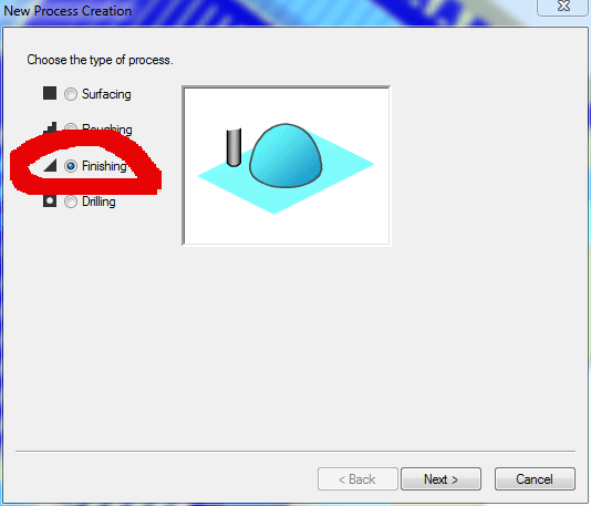
Now in this window we need to select finishing operation and follow furthur steps as above
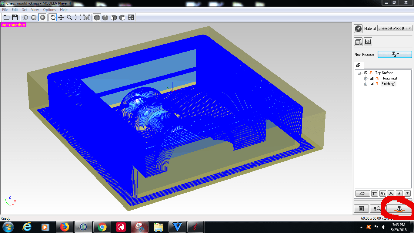
Now after this step we need to export the tool paths in the form of G codes ..... for that click on the create tool path option marked in the snap
Now soon as we click on OK we can select the destination folder and save the tool paths
Download CAM FilesMilling the Mould on SRM 20
Now the next step would be to mill out the mould ......
Follow these steps to do so
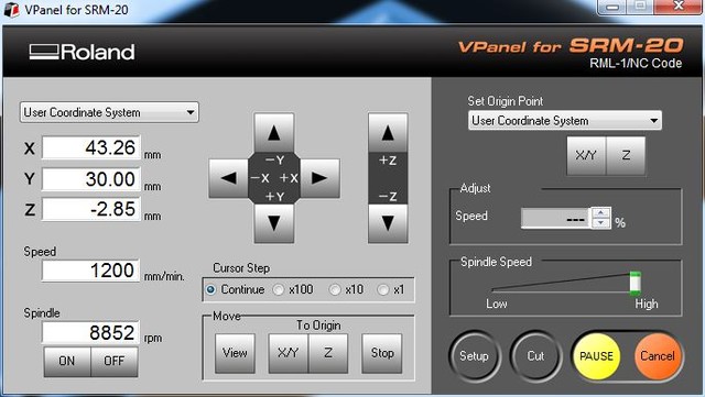
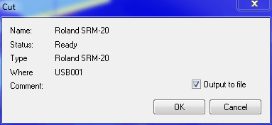
Using this V panle for SRM20, we need to set the origin and then we need to give it the cut commands followed by the tool path files we have generated ......
Note
Firstly Roughing has to be done and then afterwards finishing would be done
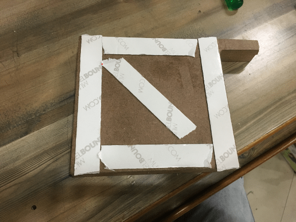
For the material I choose MDF as its quiet soft to mill and was available in lab, Use strong double sided to fix the board on the bed of the machine
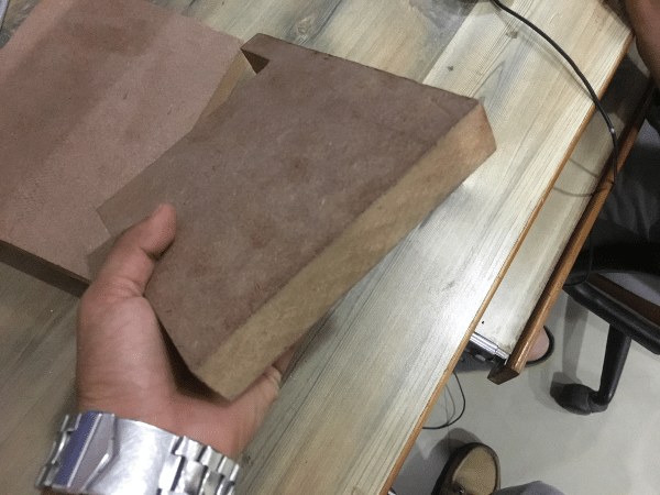
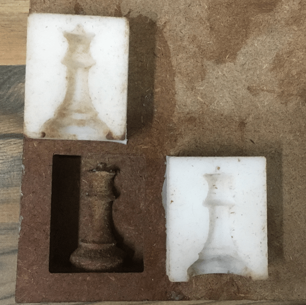
Now after milling
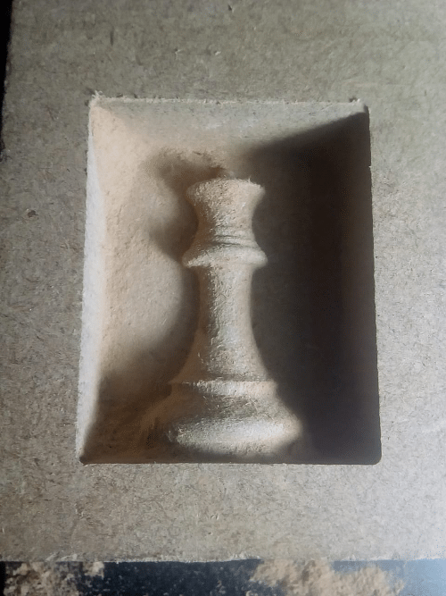
The quality turned out to be good
Now since I was also satisfied with the quality of the mould I Decided to move ahead with making soft silicon mold for the same.
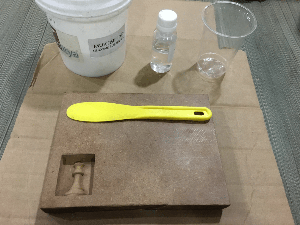
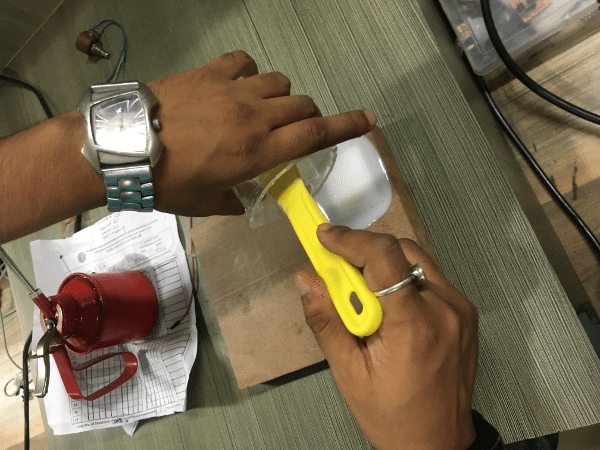
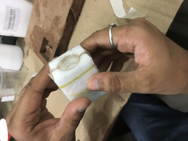
Normally the silicon material is not hard.... for that we would be needing curing agent ...... which works as a hardner...... we need to very much careful while adding curing agent .... as too much of it would harden the material immediately ..... the ratio is about 40ml of curing agent in 1 KG of silicon.
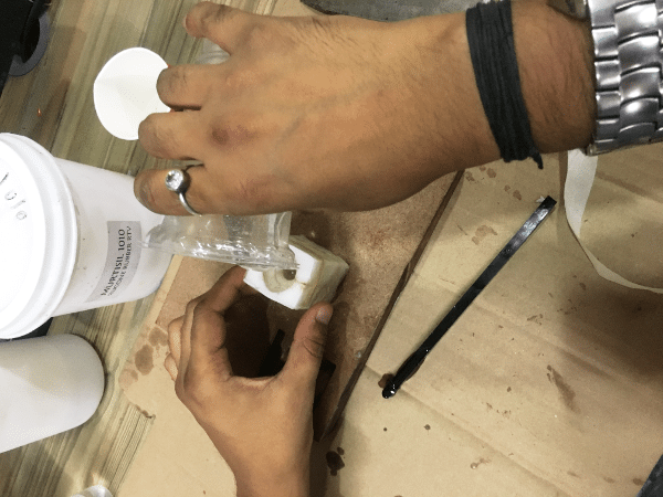
Pouring the mix in the mould
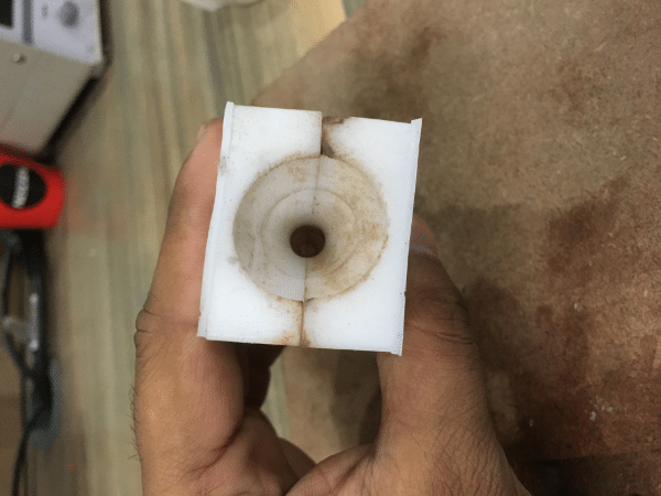
We need to make 2 copies of the same mould as the main piece has to be made in two pieces
Now we need to attach both the moulds together to make complete piece, I used rubber bands to hold them together... but still there may be chances that the epoxy may leak from the joint..... so to cope up with this problem I taped around it all.
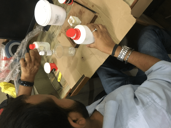
Now it was time to fill it with transparent epoxy ...... we need to take care of the hardner .... as in case of this epoxy we need to add 1 part hardner for 2 parts of epoxy and then mix them well
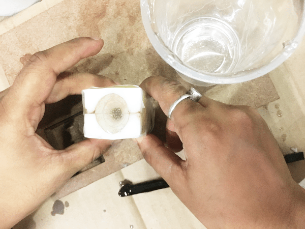
Now we'll leave this for 24 hours minimum and then we can upack the mould
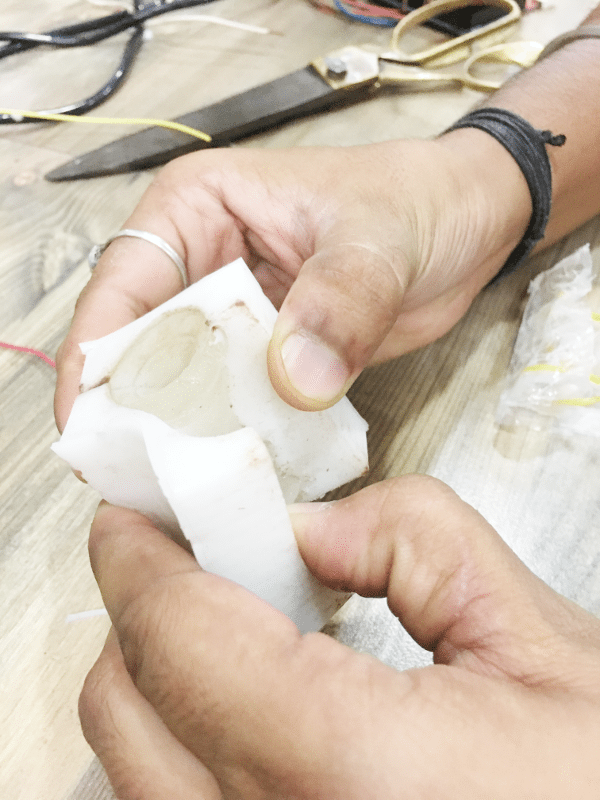
Unpacking
Overall Experience / Observations
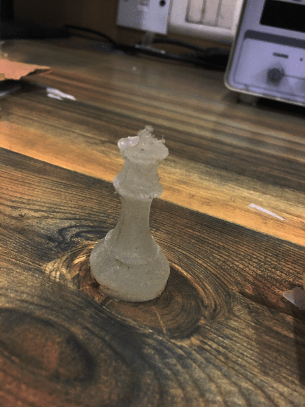
My Overall experience this week was awesome ....... its like a new type of candy I am having ....... everystep was suspense...... because I didn't know what would be the output ...... plus this assignment opened my doors to the product packaging..... Now I have a clarity how bodies of the products are made ...
1. I was expecting a transparent finish of the chess piece but it turns out to be opaque..... it may be fue to the rough surface of the soft mould..... to get that transparent finish we need to sand it with 400grade Ambri paper .. but it was not available to I left the piece as it is.....
2. The shape of the piece is a bit mis-oriented.... it may be due to the soft mould ... if it would have been a solid mould then this problem wouldn't arise ....
3. I see some air bubbles at the surface of the chess piece due to which its transparent at that place ...... I dont know how to get rid of them
4. The chess piece it a bit soft even after 48 Hours ...... It may be due to less hardner which I have added ....
Download Chess Mould Files Download CAM Files