week 8: computer-controlled machining
assignment for the week
1. Test runout, alignment, speeds, feeds, and toolpaths for your machine (CNC router)
2. Make something big
learning outcomes
1. Document the process of design and production to demonstrate correct workflows and identify areas for improvement, if needed
have i
1. Explained how I made my files for machining (2D or 3D)
2. Shown how I made something BIG (setting up the machine, using fixings, testing joints, adjusting feeds and speeds, depth of cut etc)
3. Described problems and how I fixed them
4. Included my design files and 'hero shot' photos of final object
testing runout, alignment, speeds, feeds, and toolpaths for our CNC router
All tests, explained below, were performed on a flat bed CNC Router, SIL-1325 CNC Router, from Suresh Indu Lasers Pvt Ltd (Pune, Maharashtra, India) using a 6 mm flat up-cut end mill. All test cuts were made on _____ plywood 19 in thick.
Neil's suggestions for making test cuts:
1. Cutting a chunk of material is good enough to diagnose all issues with the machine, e.g. a small square of wood.
2. Take a piece of stock, make a shallow cut, a deep cut, go slowly, go fast/quickly, and see how the machine responds to find that sweet spot where you are working as quickly as possible, but the machine is happy, and look at what happens if you go too fast, or too slow.
3. If you cut out a square, one is, are these dimensions the dimensions you asked for? One is, are the top, bottom, right, and left dimensions the same? But one of the questions is, if you look at the space that was cleared, how does that relate to the size of your tool? What is this material removed vs the tool size, and that's a measure of the imperfections in the machine.
4. Take your machine, cut a small square. See how the dimensions relate to what you designed. Check the runout of the machine. Check going fast and slow, small cuts, big cuts. See what it looks like to get it right and wrong. You can experiment with toolpaths that aren't just a straight line but some of these high speed toolpaths.
The following tests were performed:
1. testing kerf and runout: The tool isn't a perfect straight line, it has some degrees of freedom in the collet, and the collet might also not be straight. So, the reality is your tool wobbles a little bit, jiggles around as it goes around, and so runout is the actual diameter of what's cut. If what's cut is larger than the diameter of the tool, it is because of imperfections in how its held in the collet. And so, one of the things you have to test is the kerf and the runout.
To test for runout, we cut holes at 6 different cut depths (Figure 8.1), and measured their inner diameters. The data is as follows (Table 8.1):
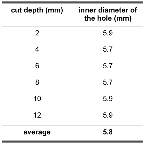
Table 8.1:
The average value of runout (from 6 trials) came to be 5.8 mm. This is a bit surprising considering our end mill is 6 mm in diameter. Anyway, a runout of 5.8 mm means that the width of material removed, or kerf (When the tool goes through, kerf is the material that is removed. That's what goes away.), is also 5.8 mm. This is a substantial amount of material being removed, and so the design of any object to be cut using the same end mill needs to consider two things: (1) dimensions in the design need to account for kerf, and (2) to get the right dimensions in the end product, the end mill needs to be offset (as these tools have a reasonable diameter), meaning while setting the toolpath (for the desired design), should the end mill cut on the outside, or inside, or on the perimeter. These are settings that can be chosen in any program used to generate a toolpath.

Figure 8.1: Test cuts for determining runout, and kerf for our 6 mm end mill.
2. testing alignment and dimensions: Make a square part, and measure did it come out square. This is to check the alignment of the machine. This in turn has to do with squaring of the machine, which is when setting up the machine, when you can adjust the degrees of freedom of your machine, making sure the axes should be at right angles. If the axes are not mutually perpendicular, and you give the machine a square design, you might end up with a pin cushion design. Also, and this happens more with the cheaper machines, the machine will drift over time, and you will need to re-adjust it periodically. In both cases, the machine will be misaligned, and cutting jobs will not come out right, and so cutting test pieces to check the machine's alignment is crucial (before giving it a long job).
To test for alignment, we cut out 50 mm by 50 mm squares in three different ways. The difference was in the toolpaths of the squares. The first square was cut along the outside of its perimeter, the next one cut along the inside of its perimeter, and the last one cut on its perimeter (Figure 8.2).
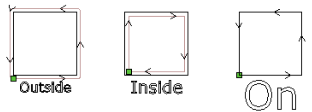
Figure 8.2: 50 mm by 50 mm test squares cut with 3 different toolpaths to test our machine's alignment.
We measured the dimensions of the cut square blocks, and our observations are as follows (Table 8.2):
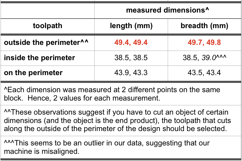
Table 8.2:
Based on our data, square block cut along the outside of its perimeter came out with the right dimensions (of 50 mm by 50 mm), within limits of experimental accuracy. Dimensions of the square block cut out along the inside of its perimeter can be explained based on our kerf data. The measured dimensions came out less than the desired dimensions by about 11.5 mm each, which is almost the same as 2 times a kerf of 5.8 mm (= 11.6 mm). The end mill is removing excess material almost equal to the kerf value from each side of the square. Moreover, we also got an outlier here suggesting our machine is not squared correctly. Lastly, dimensions of the square block cut on its perimeter can again be explained based on our kerf data. This time, the measured dimensions came out less than the desired dimensions by about one kerf value. This is because the end mill is centered on the perimeter, and so is removing excess material by about one-half of the kerf value (= 2.9 mm) from each side of the square.
Overall, dimensions of the 3 test squares can be explained on the basis of the toolpath used, and the size of the end mill. The variation in dimensions is within limits of experimental accuracy. The data suggests only minor issues, if any, with the squaring of our machine.
The other part of this test is checking the dimensions of the space that was cleared (while cutting the test squares, Figure 8.2), and how that relates to the size of our tool. We measured the dimensions of the cleared spaces and our observations are as follows (Table 8.3):
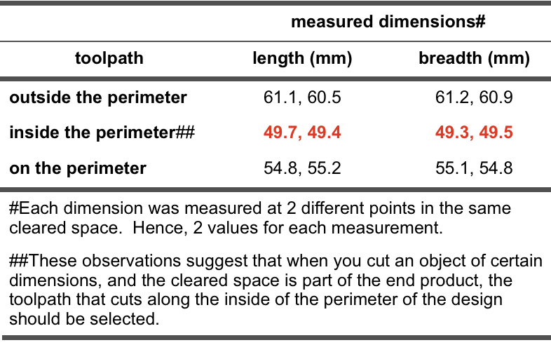
Table 8.3:
Based on the data, space cleared on cutting a square block cut along the inside of the square's perimeter came out with the right dimensions (of 50 mm by 50 mm), within limits of experimental accuracy. Dimensions of the space cleared on cutting a square block along the outside of the square's perimeter can be explained based on our kerf data. The measured dimensions came out more than the desired dimensions by about 11.0 mm each, which is a little less than 2 times a kerf of 5.8 mm (= 11.6 mm). The end mill is removing excess material almost equal to the kerf value from each side of the square, and so the dimensions of the cleared space are more, but, as stated before, the square block from the same space has the correct dimensions. Lastly, dimensions of the space cleared on cutting a square block cut on the square's perimeter can again be explained based on our kerf data. This time, the measured dimensions came out more than the desired dimensions by about one kerf value. This is because the end mill is centered on the perimeter, and so is removing excess material by about one-half of the kerf value (= 2.9 mm) from each side of the square.
Once again, dimensions of the cleared spaces can be explained on the basis of the toolpath used, and the size of the end mill. The variation in dimensions is within limits of experimental accuracy.
Our conclusion from this test is if the cut section is the desired piece/design, then "cutting along the outside of the perimeter" toolpath should be used to get correct dimensions in the final part. On the other hand, if the cleared space is part of the final design, then "cutting along the inside of the perimeter" toolpath should be chosen to get correct dimensions.

Figure 8.2: 50 mm * 50 mm square cut threeways.
3. testing speeds and feeds:
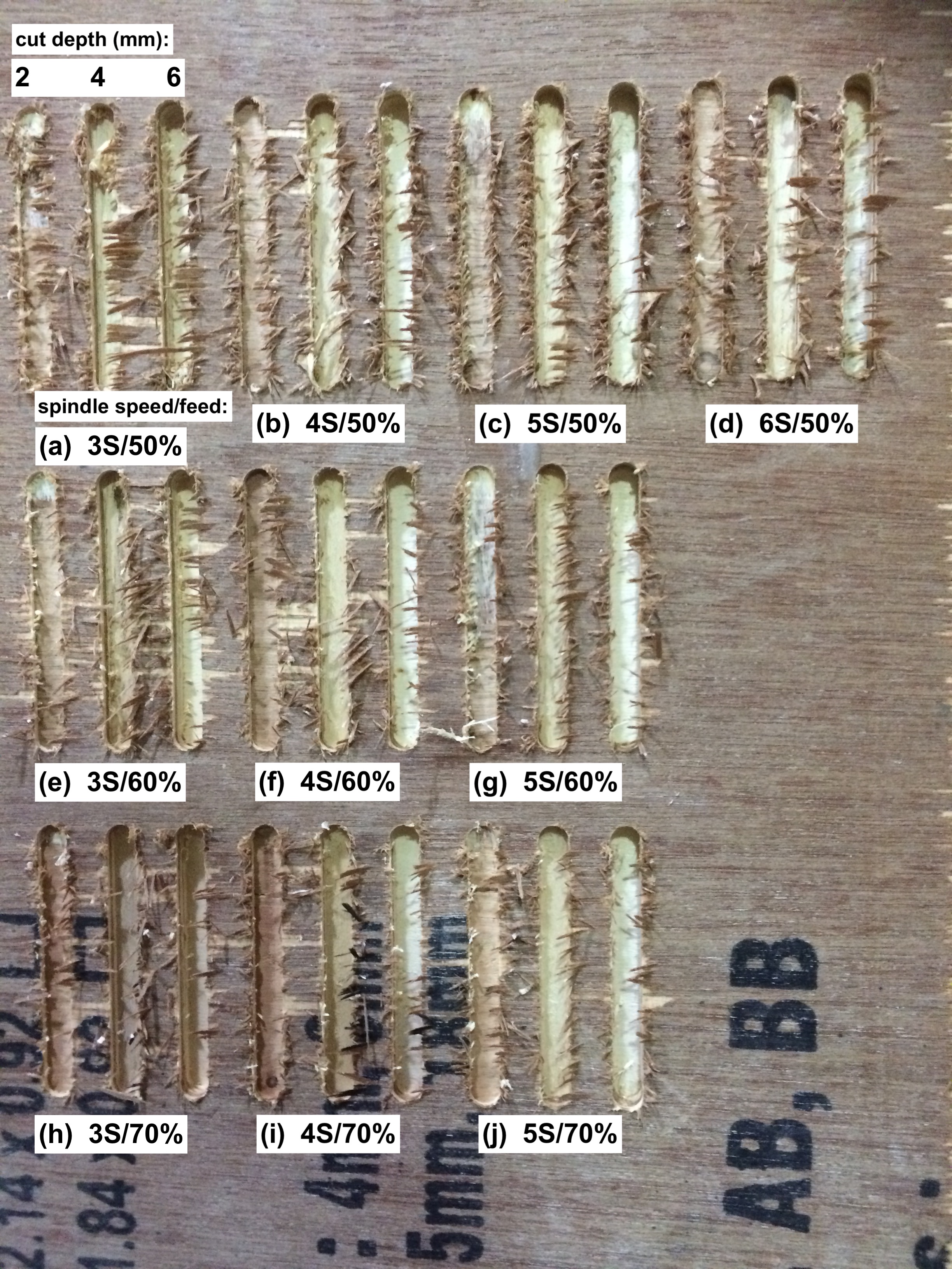
Figure 8.3: Test cuts for speeds and feeds.
4. testing toolpaths:
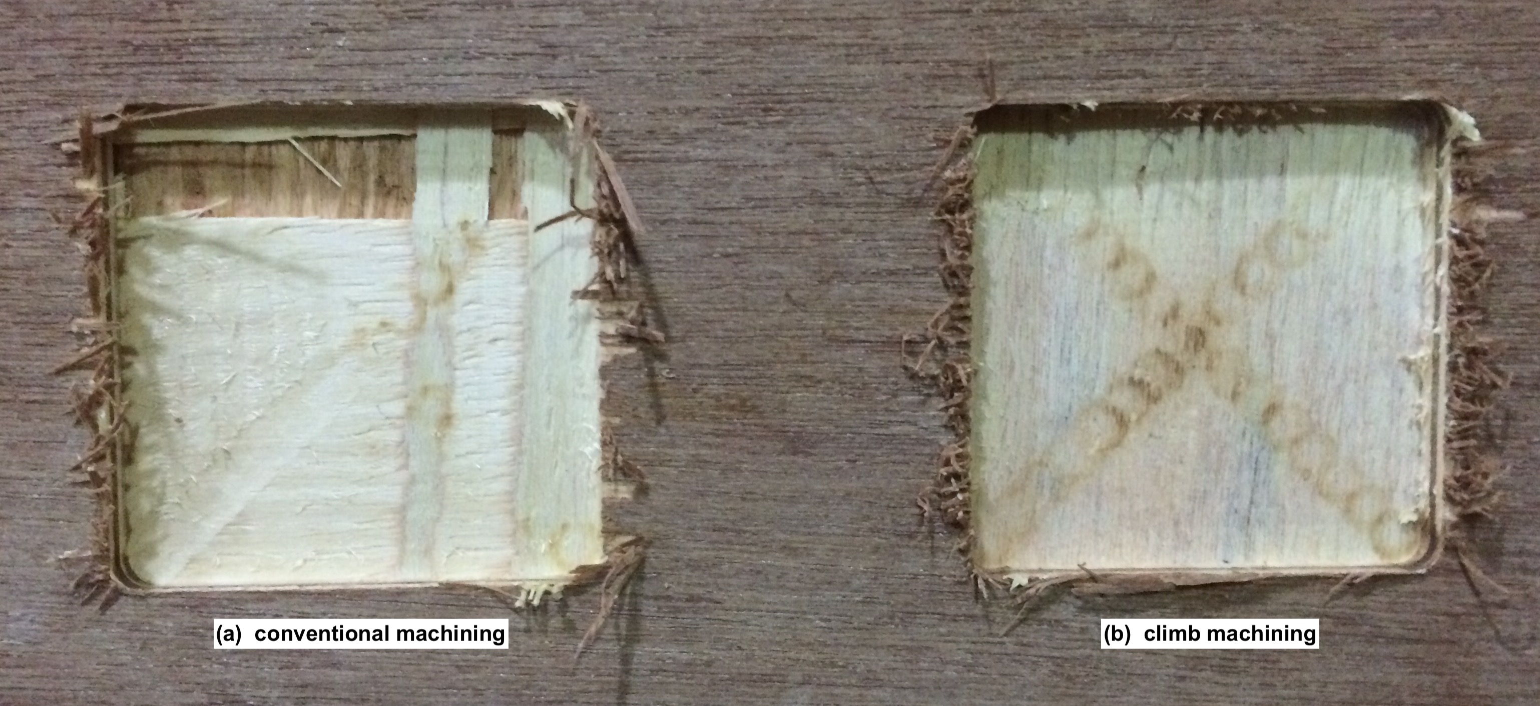
Figure 8.4: Conventional vs Climb Machining.
my goal for the week
coming up shortly ...


