1. test the design rules of your 3D printer(s)
2. design and 3D print an object (small, few cm) that could not be made subtractively
3. 3D scan an object (and optionally print it)
1. Identify the advantages and limitations of 3D scanning and printing technology.
2. Apply design methods and production processes to show your understanding.
1. Described what I learnt by testing the 3D printers.
2. Shown how I designed and made an object and explained why it could not be made subtractively.
3. Scanned an object.
4. Outlined problems and how I fixed those.
5. Included design files and 'hero shot' photos of the scan and the final object.
I installed the following programs on my computer:
1. for 3D scanning: Skanect
As Neil had explained during class that before we print anything on a 3D printer, we must test its design rules. In other words, we must know our printer's capabilities and limitations. We printed test parts for the following tests so far:
1. bridge test: This test was performed to find out the length of the longest beam on two pillars (at the beam's ends) that can be printed without any supports in-between. To do so, we printed a test part with varying beam length: 10 mm (1 cm); 20 mm; 30 mm; 40 mm; 50 mm; 60 mm; 70 mm; 80 mm; 90 mm; and 100 mm. Unfortunately, we started printing this (and other test parts), and did not realize until a lot later in the process (almost towards the end) that MakerBot's software's default setting for "supports" is ON (Figure 6.1). Hence, our test part printed out with supports under the beams (Figure 6.2), and so, we couldn't really conclude anything from this test. The test part needs to be re-printed.
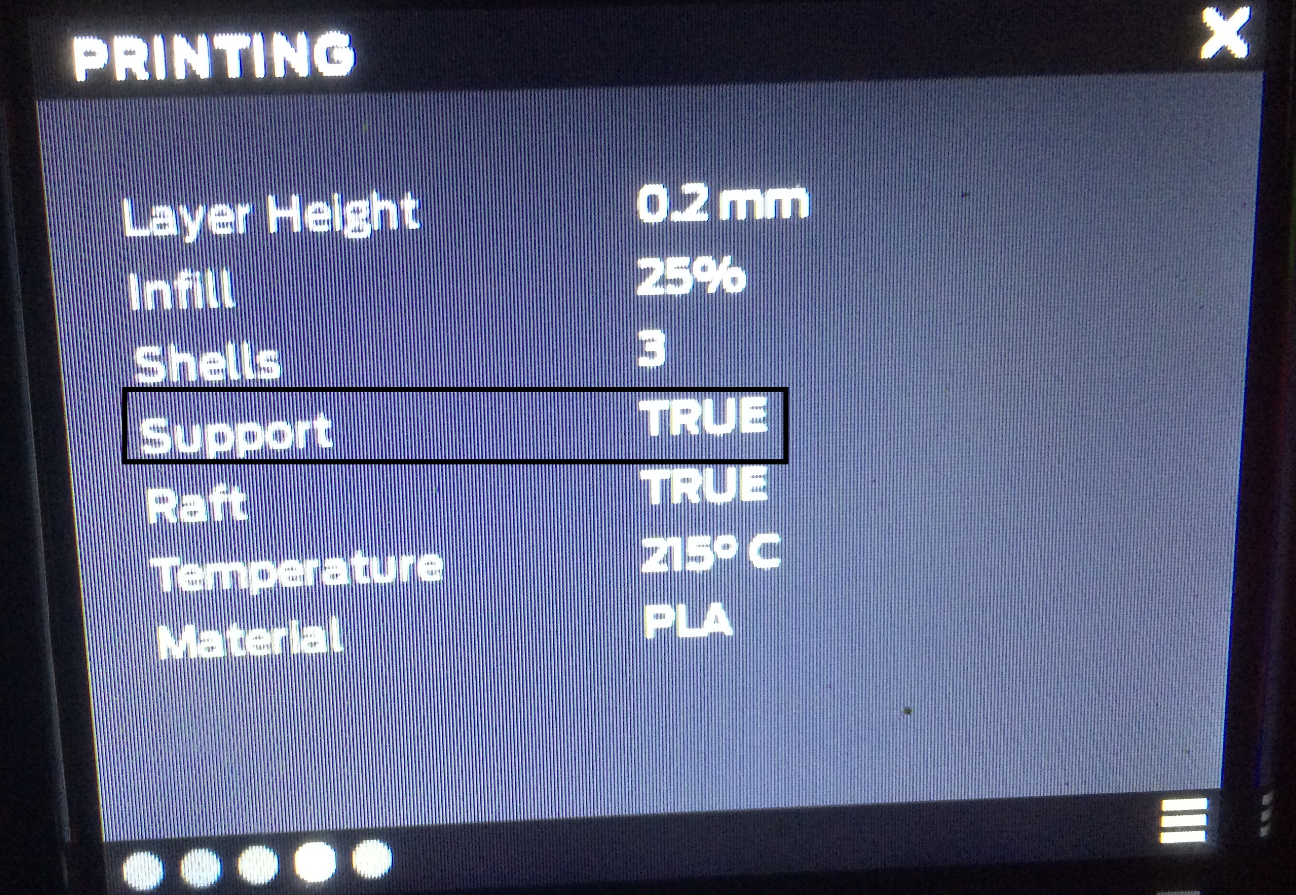
Figure 6.1: MakerBot's default print settings showing a TRUE value for the Support field, meaning the printer will print supports wherever they are necessary.
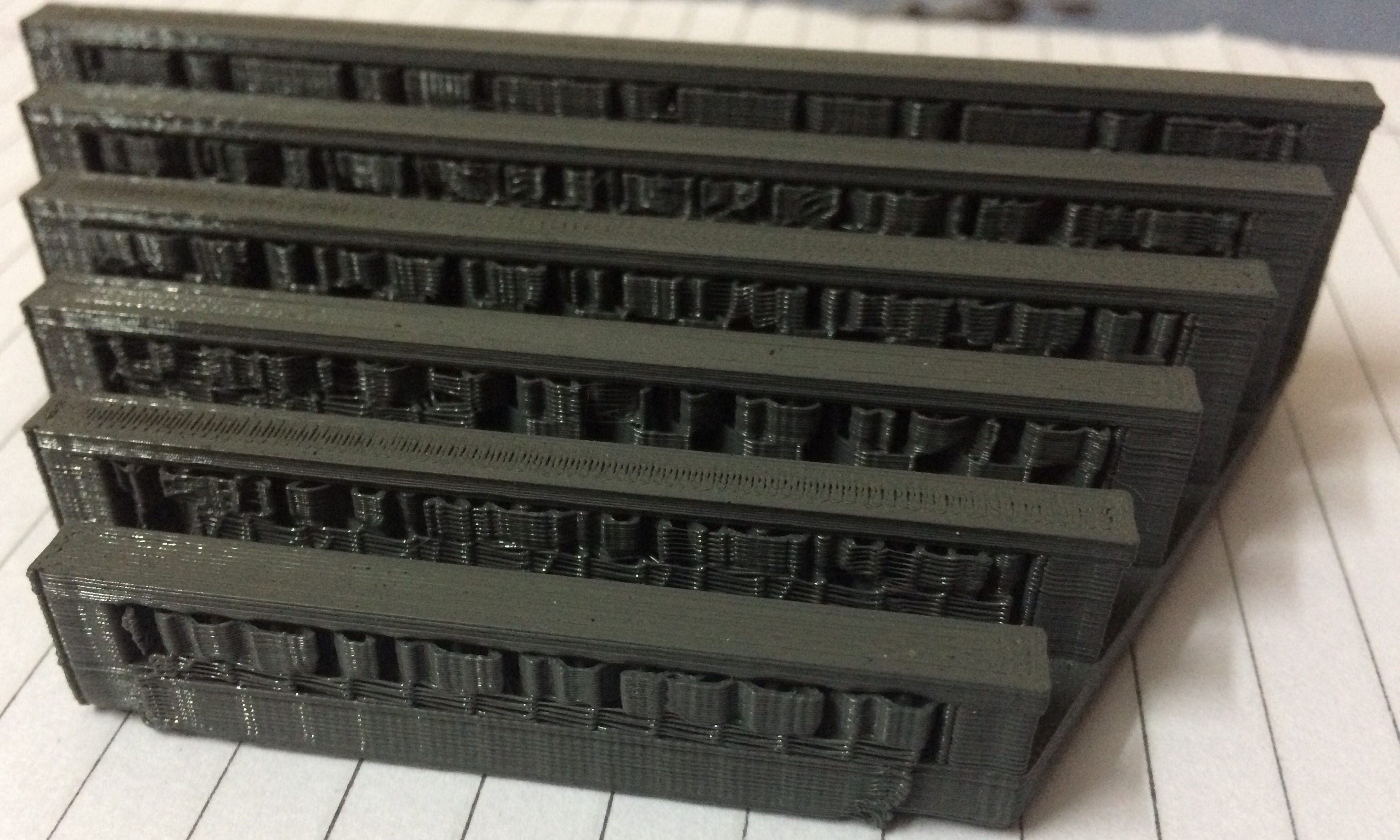
Figure 6.2: Test part for bridge test showing supports printed under beams which made this test inconclusive.
2. overhang test: To test what angles can be made without any support on the MakerBot, we printed a test part with 5 different overhangs (angles): 80 degree; 60 degree; 40 degree; 25 degree; and 15 degree. We found out that our printer can easily make parts that have overhangs of 80 degree, 60 degree, and 40 degree without any support and with a smooth overhang surface (Figure 6.3). This was not true for smaller angles, though. At 25 degree, it printed the overhang without any support, but with a rough, unfinished-looking surface. At around 15 degree, the overhang could not be printed without support.
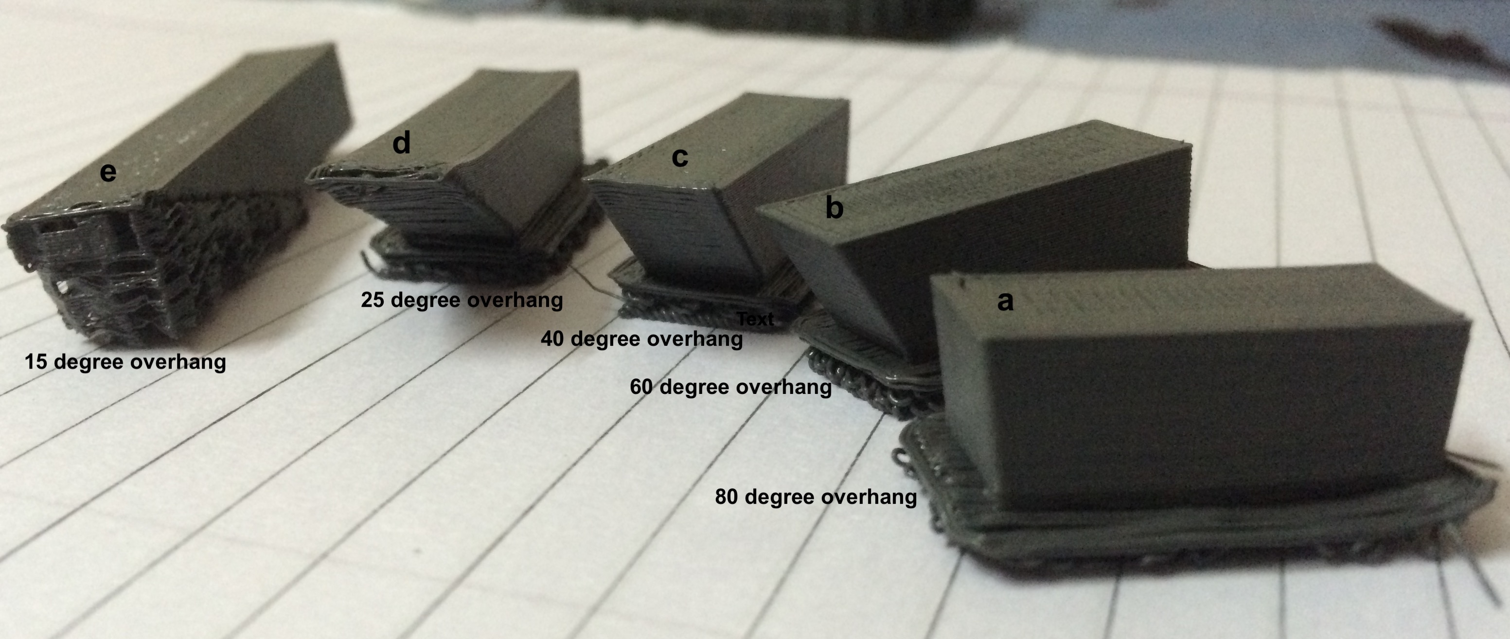
Figure 6.3: Test part for overhang test showing 5 different overhangs (angles). Overhangs of 80 degree (a), 60 degree (b), and 40 degree (c) printed out without any support but with a smooth overhang surface. Overhang of 25 degree (d) printed out without any support, but with an unfinished-looking overhang surface. Overhang of 15 degree (e) could not be printed without support.
3. wall thickness test: To test what thicknesses can be printed on the MakerBot, and will also be mechanically strong, we printed a test part with 5 different wall thicknesses: 2 mm, 1 mm, .75 mm, .5 mm, and .25 mm (Figure 6.4). We found out that all wall thicknesses printed, turned out to be strong, and none shredded. Obviously, walls with 2 mm thickness were stronger than walls with .25 mm thickness, with strength decreasing from the thickest to the thinnest walls.
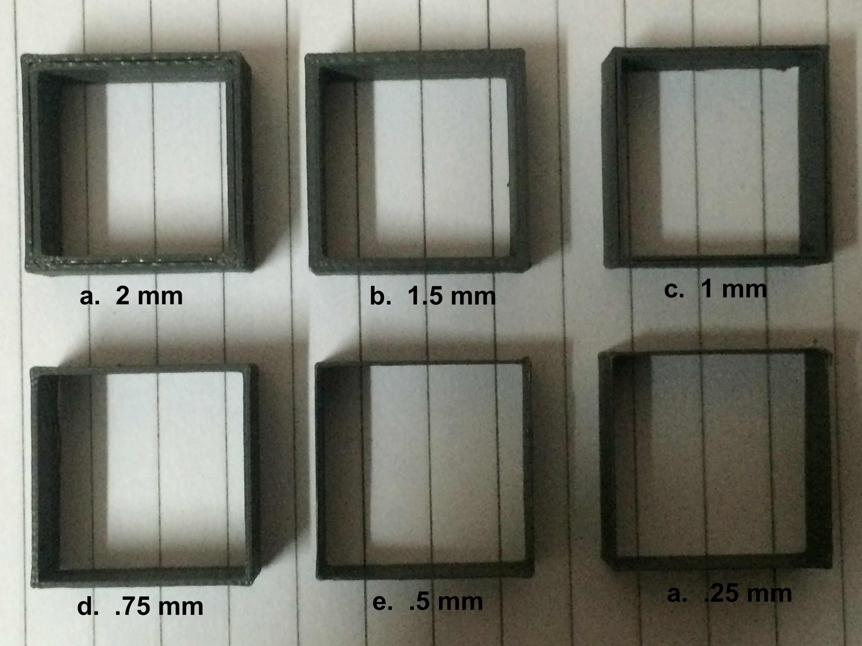
Figure 6.4: Test part for wall thickness test showing 6 different thicknesses: a. 2 mm; b. 1.5 mm; c. 1 mm; d. .75 mm; e. .5 mm; and f. .25 mm. All thicknesses printed out fine with strength decreasing from the thickest to the thinnest walls. No shredding was observed.
4. orientation test: We tested how we should orient a part to print it. For this, we printed the same object in 3 different orientations/ways varying the contact surface each time (Figure 6.5). We learnt that larger the contact surface area between the part and the raft, the better it is. Our test part was in the shape of the letter "L." When printed lying flat (maximum contact surface); and when oriented vertically up (relatively lesser contact surface), the parts turned out fine, and with good structural integrity. However, when the letter "L" was oriented upside down (least contact surface), and with a 90 degree overhang, it had to be supported. But, then the "support" feature of the printer was ON. So, we can not conclude anything about printing in this orientation (with the least contact surface). This last part needs to be re-printed.
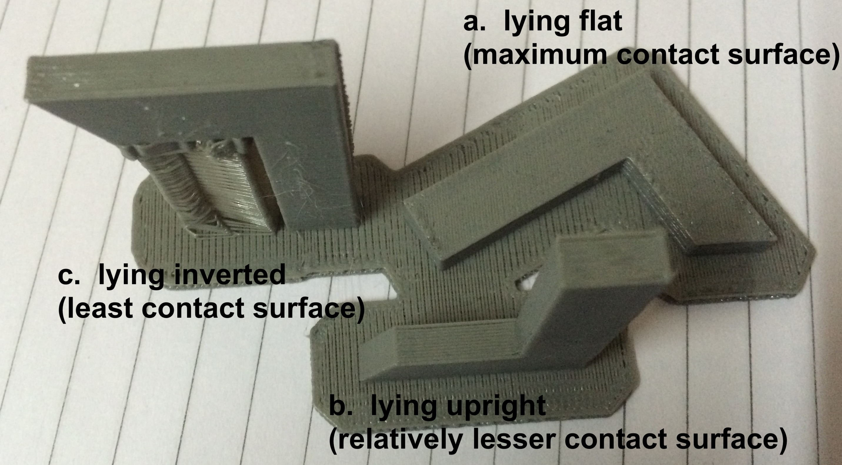
Figure 6.5: Test part for orientation test showing that when printed lying flat (a.), and when lying upright (b.), the parts printed out fine, and with good structural integrity. However, when the part was inverted, and with a 90 degree overhang (c.), the overhang had to be supported.
5. holes test: This test was performed to check what is the smallest hollow cylinder that can be printed on the MakerBot. We printed a test part with hollow cylinders with internal diameter ranging from 3 mm to less than 1 mm (Figure 6.6). We learnt that for cylinders below approximately 1 mm internal diameter, their lateral surfaces coalesced, but with diameters greater than 1 mm, the hollow cylinders printed out intact. This test also told us something about another test: At what distance from each-other, 2 printed dots don't coalesce. Dots printed approximately 1 mm apart or less will coalesce on our printer.
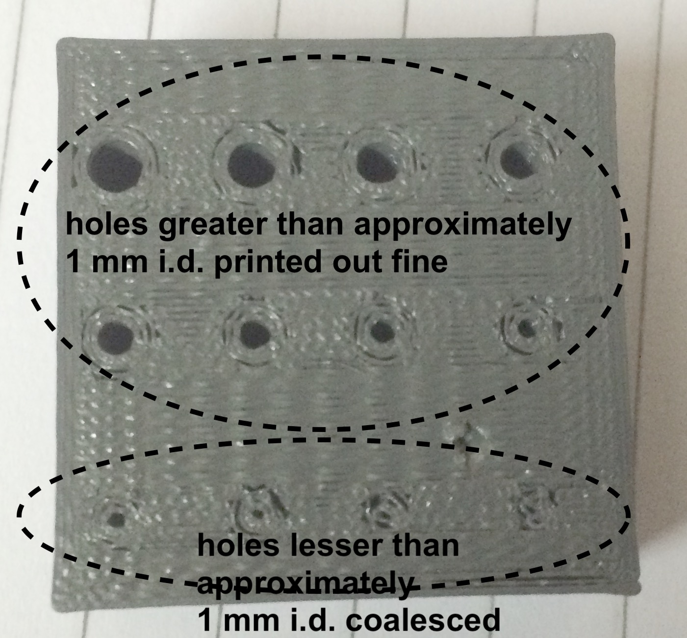
Figure 6.6: Test part for holes test showing that hollow cylinders below 1 mm internal diameter coalesced, but holes greater than 1 mm had good structural integrity.
Below are some additional design rule tests that we have not yet performed:
6. How sharp a corner can be made?
7. How small a gap/clearance can be made?
8. How does the dimensions of the actual part relate to the dimensions in the design?
9. Infill (inside support) variation test
10. What is the smallest distance at which 2 dots don't coalesce?
11. Printing speed test
12. Layer thickness (height)???
For this part of the assignment, I decided on a very simple object. I decided to print a hollow sphere. A hollow sphere can not be manufactured in one piece by subtractive manufacturing. An example is a hollow plastic ball, which is made as 2 hemispherical shells which are then joined along the circular edge. By 3D printing, an additive manufacturing process, a hollow sphere can be printed in a single piece. It was printed on a MakerBot using poly-lactic acid (PLA) filament.
The sphere was designed in Fusion 360 as follows: Create a Center Diameter Circle with a diameter of 75 mm at the origin > Using the Line tool, draw a diameter splitting the circle in to 2 halves > Using the Trim tool, erase the circumfrence of one half of the circle > This leaves you with a closed semi-circle > Using this closed semi-circle as a planar face, Revolve it along the diameter (used as an axis) > This creates a hollow sphere centered at the origin, and with a diameter of 75 mm.
The sphere was exported as a .stl file for 3D printing. The .stl file was then opened in MakerBot's print software wherein print settings, particularly raft size and support, were modified. Infill was also modified to none or 0 (zero). Final print settings were then saved as a .makerbot file to be used for printing.
Although, a very simple object, turns out 3D printing it is not that simple. My initial trials to print the sphere kept failing. What I learnt from these failed initial trials is that because a sphere has a very small surface (theoretically, a point) in contact with the build plate, the structure becomes unstable very quickly, and detaches from the build plate. A very small raft (about 10 mm diameter) and no or minimal support were also reasons for destabilization of the structure. Having learnt that, I performed another trial with a much bigger raft as the base and a lot more structural support, and that worked out really well. I was able to print the hollow sphere in one go after making those changes in the print settings. Here is the result (Figures 6.7, and 6.8)
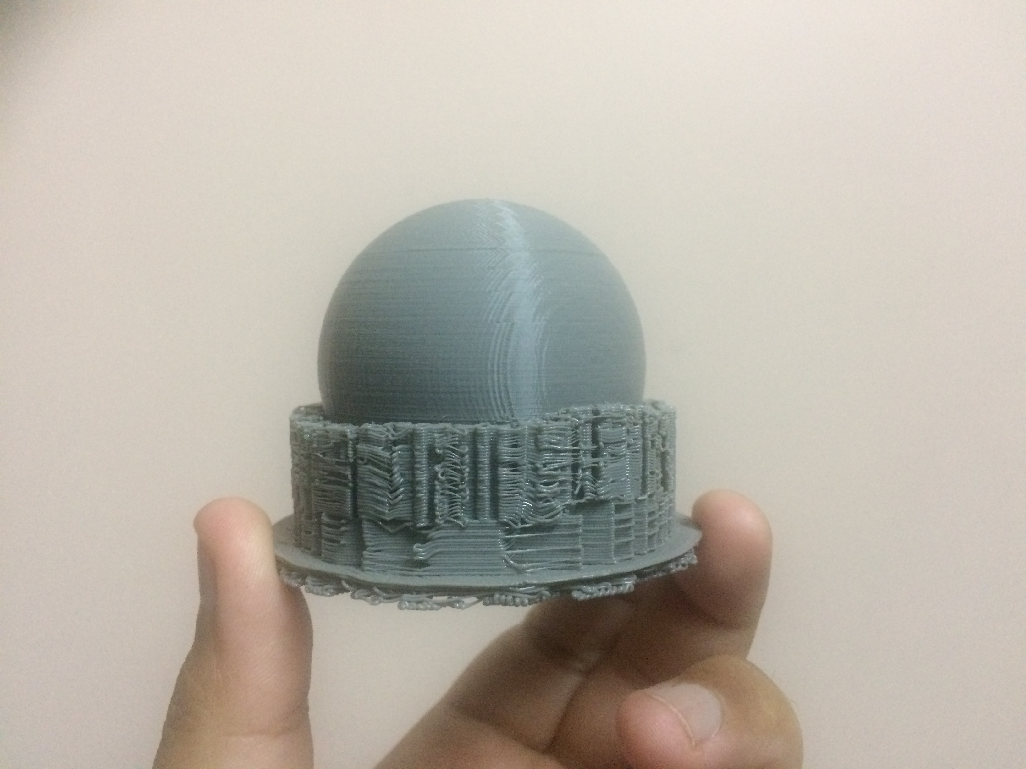
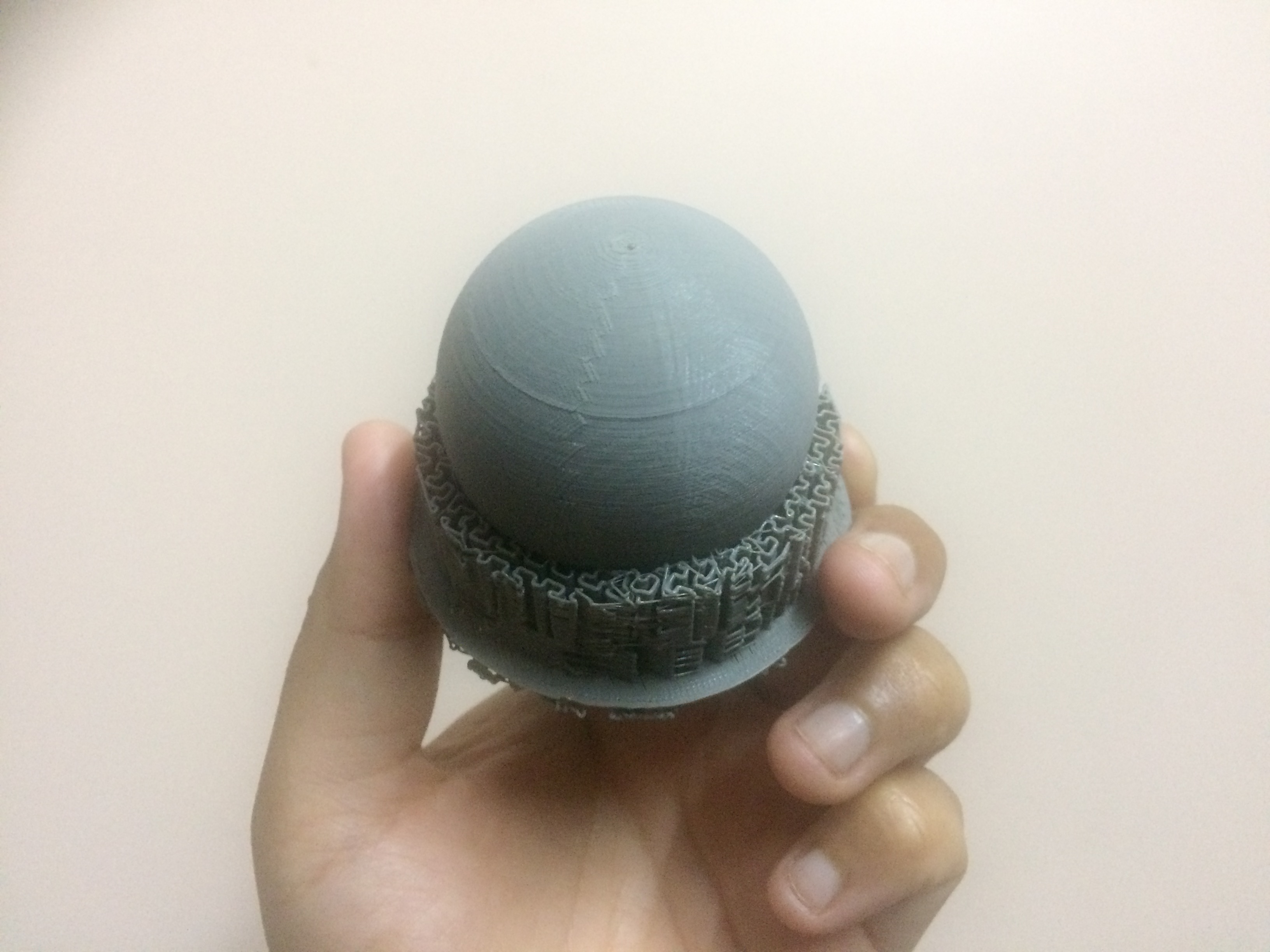
Figure 6.7: A printed hollow sphere with substantial raft and supports, 2 different views.
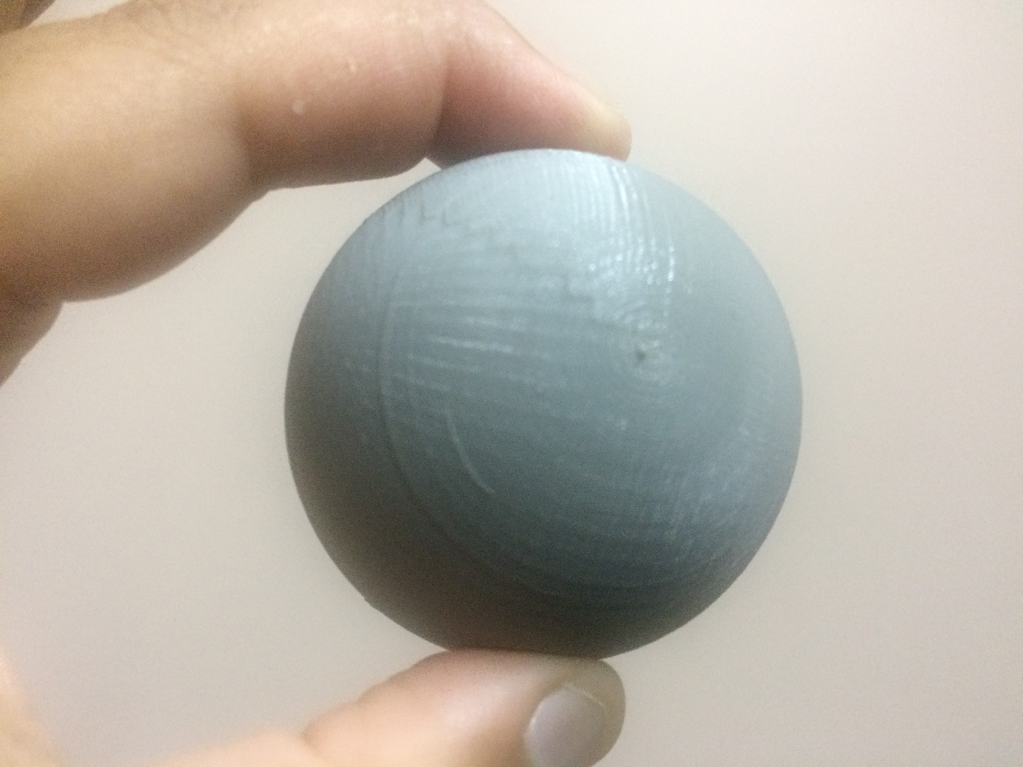
Figure 6.8: A printed hollow sphere (raft and supports removed).
Here is a short film captured during printing. It was captured from the top of the instrument after removing the top cover of the instrument.
A solid sphere can be easily manufactured as one piece by subtractive manufacturing. A hollow sphere, on the other hand, can not be manufactured as one piece by subtractive manufacturing. The problem is how does one hollow out a solid sphere without splitting it in to two (equal or unequal) parts? The answer is you can not. The solid sphere has to be split, the two parts are then hollowed out, and the shells are then joined together at their circular edges to obtain a hollow sphere. This is where 3D printing, an additive manufacturing process, comes in, and can be used to make hollow spheres as single objects.
I used Microsoft's Kinect Sensor for Xbox 360 to scan myself. I performed these scans in 2 different ways: (1.) keeping the sensor stationary and myself rotating on a desk chair in front of the sensor (Figure 6.9, and its .stl file), and (2.) keeping myself stationary and the sensor moved around me manually in a circle (approximately). A raw (Figure 6.10, and its .stl file) and processed (Figure 6.11, and its .stl file) image of the second scan are presented below.
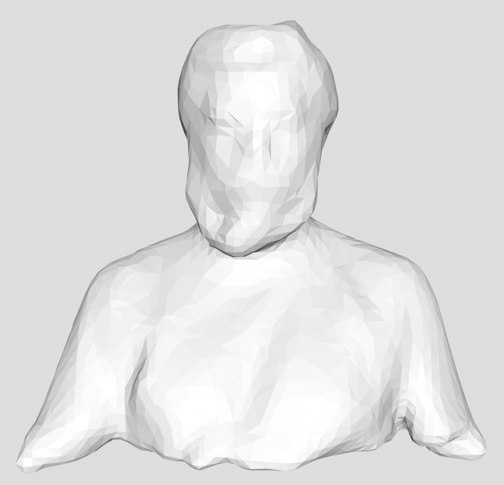
Figure 6.9: A processed (holes filled) scan originally performed by keeping the sensor stationary while I rotated on a desk chair in front of the sensor.
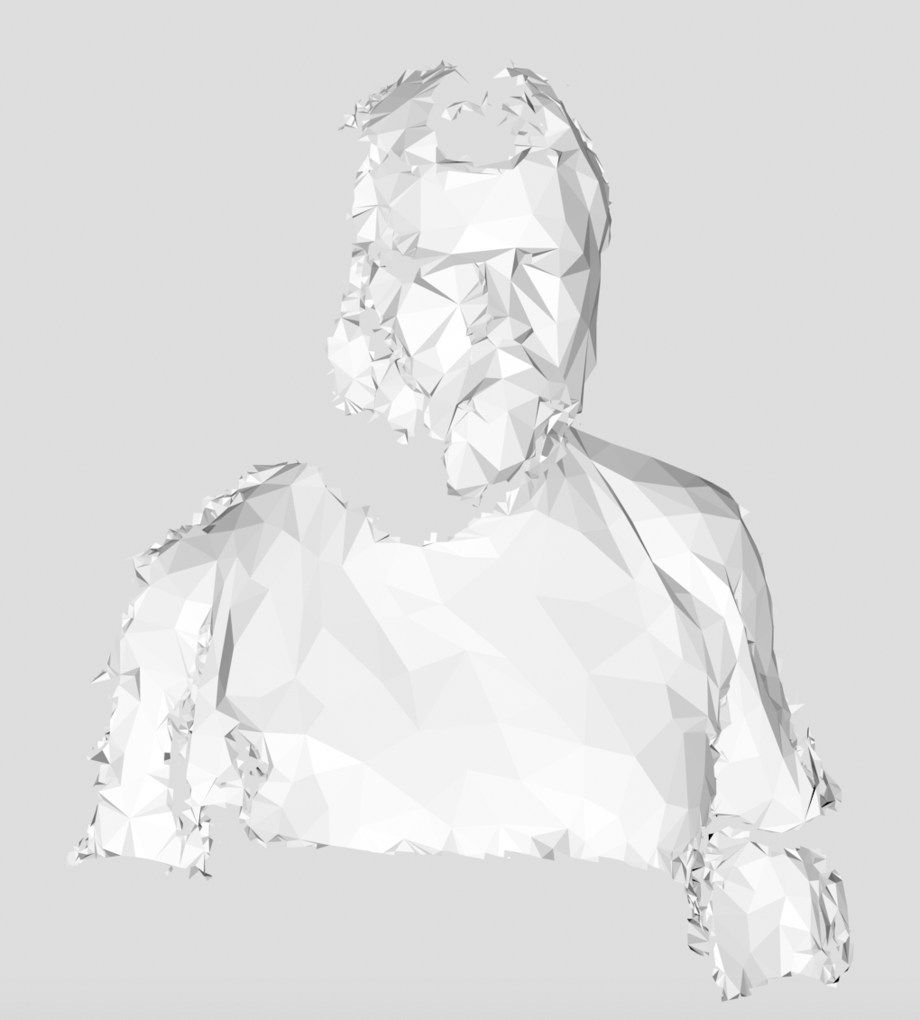
Figure 6.10: A raw scan performed keeping myself stationary and the sensor moved around me manually in a circle.
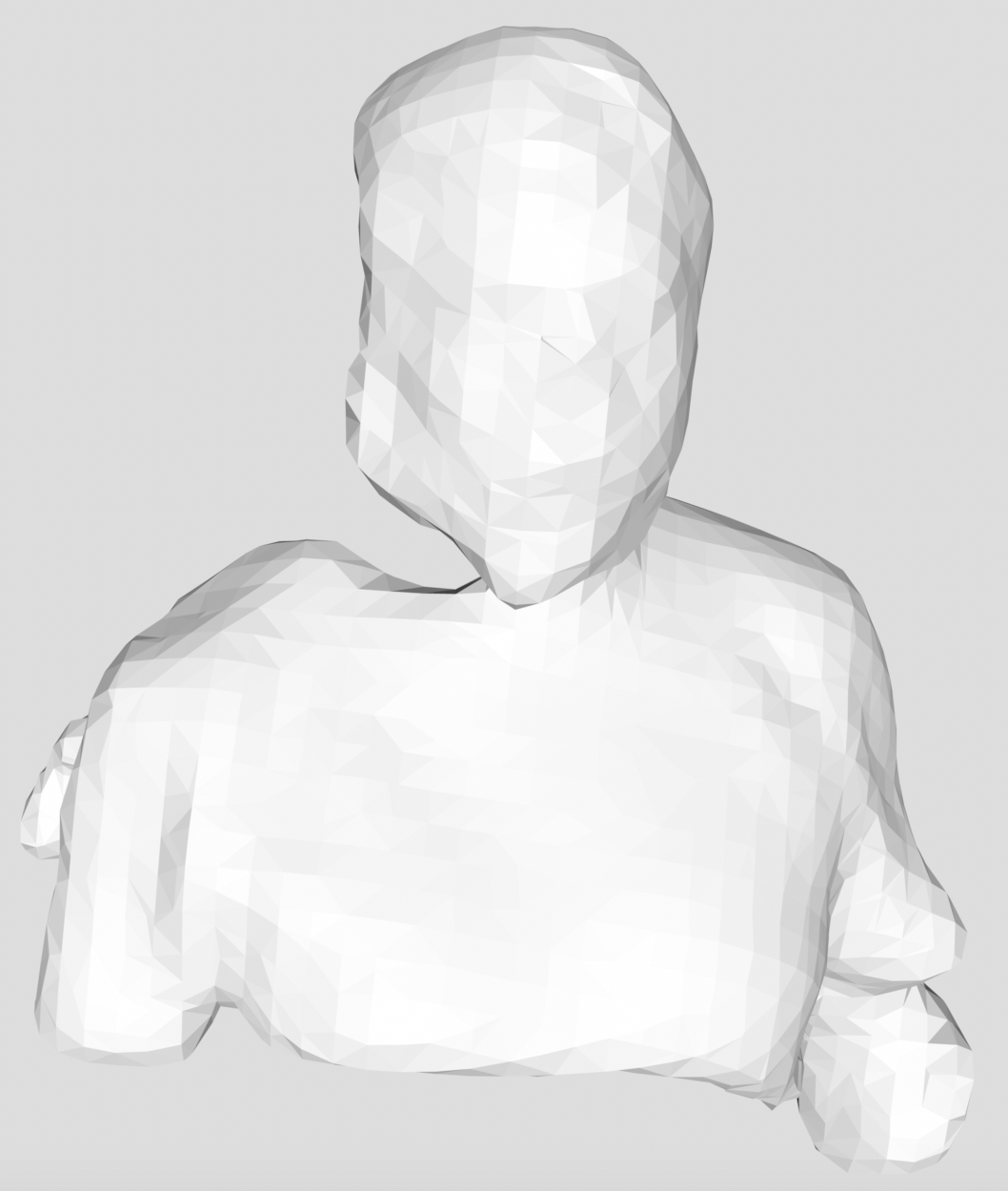
Figure 6.11: A processed (holes filled) scan originally performed keeping myself stationary and the sensor moved around me manually in a circle (of 6.10 above).
After scanning myself, I was excited to 3D print a statuette of myself. Figure 6.12, Top and Bottom, shows front and side views, respectively of the statuette. The corresponding (or parent) scan is shown in Figure 6.9 above. The scanned image was exported as a .stl file. The .stl file was then opened in MakerBot's print software wherein print settings, particularly raft size, support, and infill, were modified. Final print settings were then saved as a .makerbot file to be used for printing. The statuette was printed on a MakerBot using PLA filament.
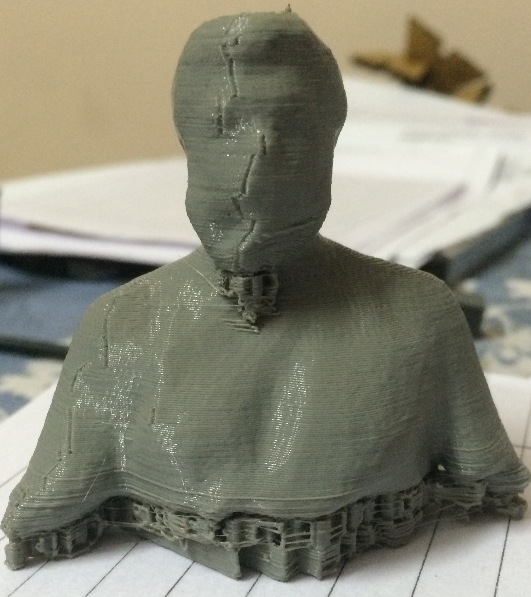
top
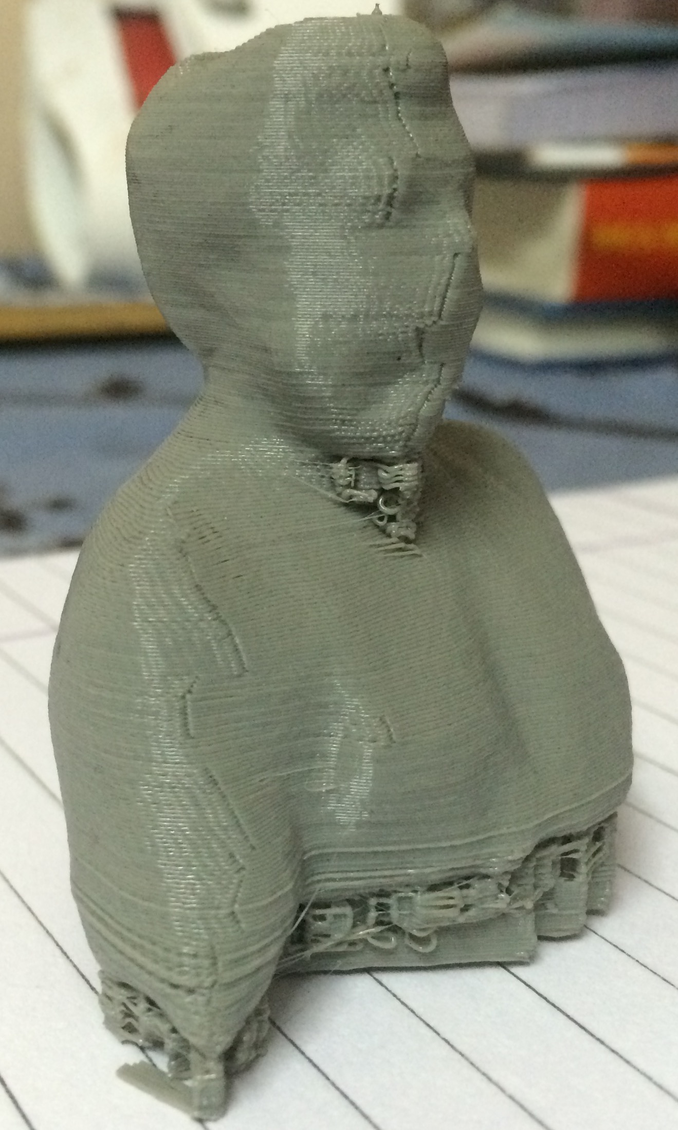
bottom
Figure 6.12: Front (top) and side (bottom) views of my 3D printed statuette.