Two weeks ago, I designed and made a version of the
Hello Echo
board. This week, I will be making it do stuff using the C
programming language and Arduino IDE.
TODOs
☑ Read an AVR microcontroller datasheet
☑ program your board to do something, with as many different programming
languages
☑ Document the programming process
☑ extra credit: experiment with other architectures
ATTINY44A
The documentation for Atmel’s
ATtiny44A
MCU is a whopping 286 page pdf. I dived in to find out what
the chip can do and how it works.
Microcontroller Data Sheet
I learned that so many information about the product is included in Data
Sheet.
I could not understand as I expect, but I found some information related
this week assignment which used C programming.
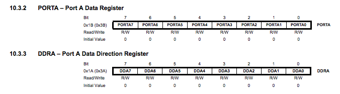
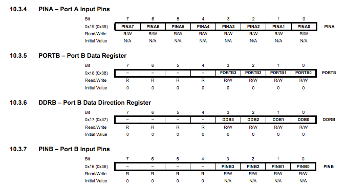
10. I/O Ports
10.1.1 Configuring the Pin
Each port pin consists of three register bits: DDxn, PORTxn, and PINxn. As
shown in “Register Description” on page 66, the DDxn bits are accessed at
the DDRx I/O address, the PORTxn bits at the PORTx I/O address, and the
PINxn bits at the PINx I/O address.
Datasheet
There is really a lot of information in the rest of the
datasheet. Too much for a beginner like me to actually get
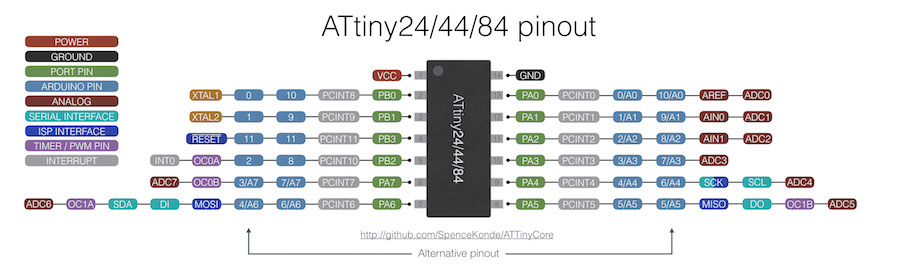
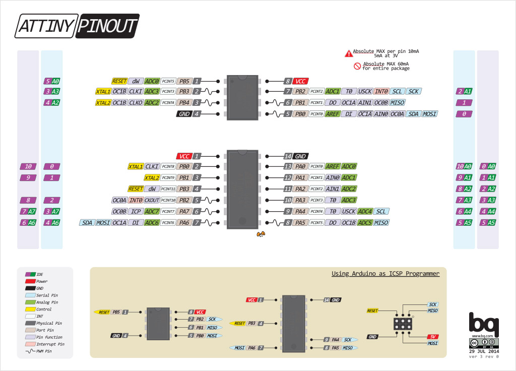
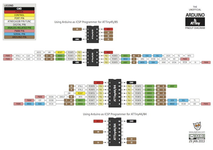
into unless I know what I’m looking for. The Pin
Configuration and Pin Descriptions in Section 1 are
important - PighiXXX has created very nice colour-coded
pinout diagrams for many processors including the ATtiny
family, including pin mapping for the Arduino IDE:
PROGRAMMING THE MCU
My first step was to make sure I had the necessary
toolchain for programming the chip -avr-gcc and avrdude.
Using homebrew on Mac OSX, pull avr-binutils
and avr-gcc:
brew tap osx-cross/avr
then install avr-libc:
brew install avr-libc
and avrdude
brew install avrdude --with-usb
Now I could go ahead and program the microcontroller. As a
first test, I downloaded Neil Gershenfeld’s hello echo
example
C
and
makefile
code, and followed this
tutorial
to compile the code, set the fuses and program the board.
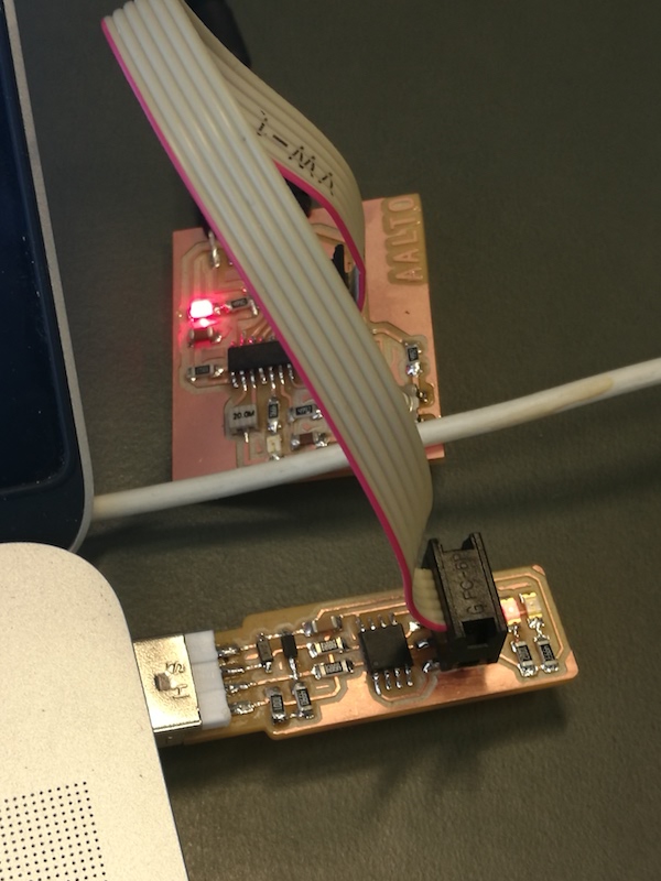
The Hello Echo and FabISP boards connected together and
to a computer with USB and FTDI
With both the C code and makefile in my root directory, I
compiled the code:
make -f hello.ftdi.44.echo.c.make
then setting the fuses, to set the clock to 20MHz using the
external crystal:
make -f hello.ftdi.44.echo.c.make program-usbtiny-fuses
.hex and .out were made.
and programmed the microcontroller:
make -f hello.ftdi.44.echo.c.make program-usbtiny
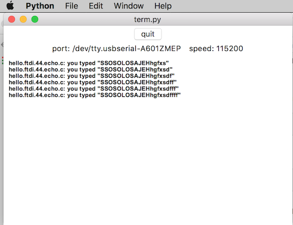
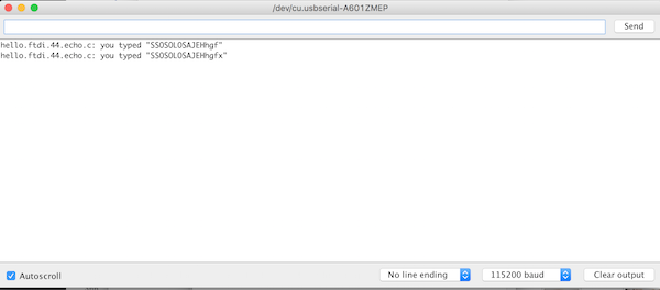
When FabISP writes program, USB-Serial FTDI supplies 5V to echo hello-world
board. After programmed, signals go from PC to echo hello-world board via
USB-Serial FTDI. To see if we have a serial communication we will use python.
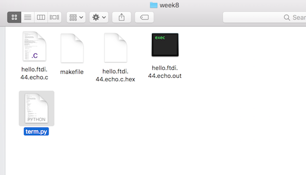
How to run "term.py"
Neil wrote this python program for serial communication and can be downloaded from the class page.
term.py
I move it to the same folder as everything else. Then run "term.py" from
terminal.
Before using the program we need to make sure that we have all we need and pythone is working on our work station.
As Neil discribed in the class, we can devide the Arduino into five major parts. The IDE, library, hardware, bootloader and a header.
A bit of setup is needed before you can program an AVR
microcontroller with the Arduino IDE. Following this tutorial from MIT on
hightechlowtech.org, I installed the ATtiny board
extensions for Arduino, and set my configuration under
for programming an ATtiny44
using a USBtinyISP and use the bootloader to load the program.
Bas made a really nice preserntation on programming with Arduino IDE.
This
post
by Mayank on maxembedded.com was also helpful.
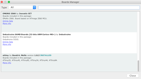
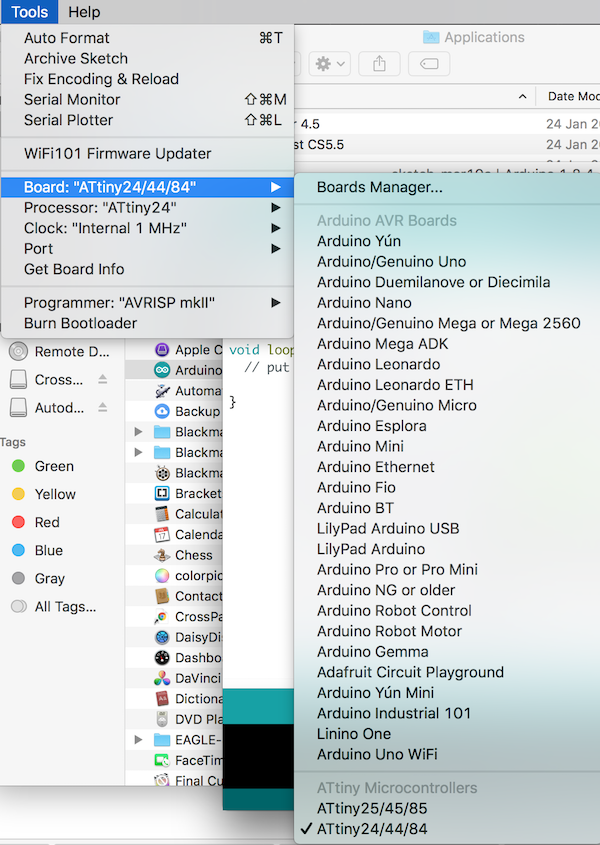
Adding the Attiny board from the board manager
Now you can find the board from the board manager
Adding the Attiny board from the board manager
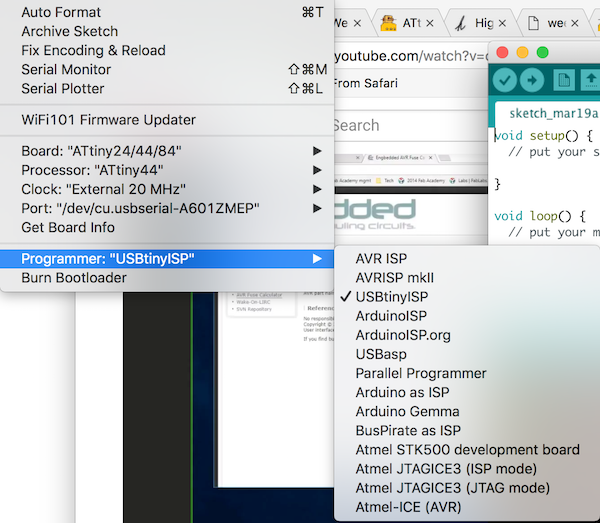
We need to set the programmer to our ISP programmer
Set the programmer to be the USBtinyISP
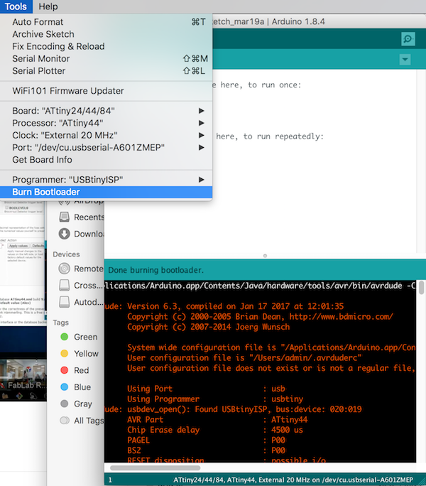
Bootloader uses internal avirdude
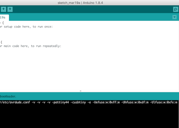
Fuse settings for Ardunio avirdude can be seen on the verbose output
Fuse settings for Ardunio avirdude can be seen on the verbose output
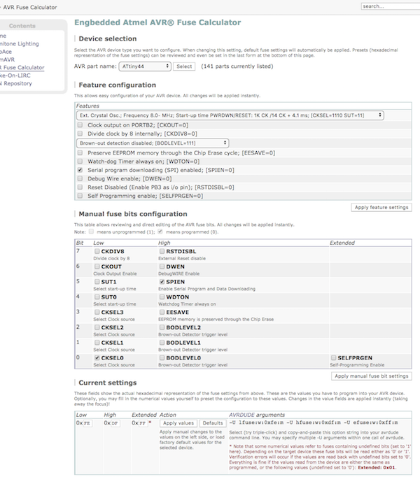
After that I wanted to check how the fuses were programmed. I used this online fuse calcultor
in order to see which are the possible values you can modify with the
fuses. In addition, I read the section 19.2 ATTiny44 data sheet
in order to understand the meaning of the different bits. Please note that
programming a fuse bit, means to put it to 0 and unprogramme it means put
it to 1. With the fuses you can select, among other, following settings:
Clock to be used.
Since we want to use an external clock we need to modify the fuses.
Accordding to section 6.2 in
ATTiny44 data sheet
, you need to set the CKSEL bits to 0 (CKSEL= 1110)
When external clock source is selected, start-up times are
determined by the SUT Fuses as shown in table 6.3 from ATTiny Data
Sheet. In this case, I used the default settings coming in the fuse
calculator, that turn out to be the most conservative ones, recommended
for "Slowly rising power". The SUT fuses were set to 01
Initial clock preescaler
. If CKDIV8 fuse is programmed (CKDIV8= 0, then, by default any external clock is divided by 8.
That is, accordding to section 6.5.2 of the
ATTiny44 data sheet
"the divider divides the master clock input to the MCU, the speed of
all synchronous peripherals is reduced when a division factor is used."
"The Application software must ensure that a sufficient division factor
is chosen if the selcted clock source has a higher frequency than the
maximum frequency of the device at the present operating conditions".
The frequency preescaler can be modified later using the CLKPS register.
Allow the clock signal to be an output in a data pin.
Currently it is disabled: CKOUT=1
Enable SPI and data downloading by setting the SPIEN fuse to 0
Activate the Brown-out detection, that is, a dip in the power
supply voltage. If it happens, the microcontroller automatically reset.
Setting the BODLEVEL fuses accordding to table 20.5.2 in
the
ATTiny44 data sheet
. Actually, I am not plannig to use this feature so I kept the default
values: 111
I left the rest of the values to its default value. Inserting the values
from the this online fuse calcultor
, I got the following values for the fuse bits to use in the avrdude
command:
I am accessing/modifying the lfuse/hfuse/efusememory
I am performing a writing operation: the w parameter
I am using the immediate mode; actual byte values specified on the
command line (m parameter). This is useful to programming
bits
Open Serial Console and set the same bps.
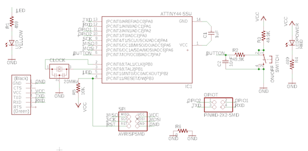
Here’s the pin connection to the chip pin that we are setting as an out put LED
Pinout of ATTiny 44a for Arduino IDE. Pin numbers are marked in brown. This image was obtained from:
pighixxx
For the above we can deduce that PB-2 on ATTiny 44a is translated as PIN-8 and has to be set as an output to the led. Similarly the PA-7 on the ATTiny 44a is translated to be PIN-7 and is by default set to be input
I then created the following sketch to make the LED blink every second. Note that I am using, in this case the internal clock. To that end I setup 8MHz in the Tools > Clock and after that Burn the bootloader to modify the fuses.
    $ const int LEDPIN = 8;
void setup() {
  pinMode (LEDPIN, OUTPUT);

}

void loop() {
    digitalWrite(LEDPIN, HIGH);
    //Wait for 1000ms
    delay(1000);
    digitalWrite(LEDPIN, LOW);
    //Wait for 1000ms
    delay(1000);
}
The code worked and the LED blinked :)!! I am very happy now.
I then created the following sketch to run the code to turn on the LED just when the button is pressed and stays on for 2000ms running on internal clock at 8Mhz. On my board I have a pull-up resistor for the LED So I don't have to use the internal pull up. The code I run was the following
    const int LEDPIN = 8;
const int BUTTONPIN = 7;

    void setup() {
  // LED as an output while button as an input
  pinMode(LEDPIN, OUTPUT);
  pinMode(BUTTONPIN, INPUT);
}

void loop() {
  //Check if button is pressed (its value is 0 because the button has a PULL-UP resistor)
  int button = digitalRead(BUTTONPIN);
  if (button == LOW){
    digitalWrite(LEDPIN, HIGH);
    delay(2000); // stay on for this time after the bptton press
  }
  else {
    digitalWrite(LEDPIN, LOW);
  }
I then wrote an Arduino sketch with similar functionality
to my LED Button example, but with a fast blink speed when
the button is not pressed, and a slow blink speed when it
is:
 The Hello Echo and FabISP boards connected together and
to a computer with USB and FTDI
The Hello Echo and FabISP boards connected together and
to a computer with USB and FTDI
 Adding the Attiny board from the board manager
 Adding the Attiny board from the board manager
 Set the programmer to be the USBtinyISP
 Bootloader uses internal avirdude
 Fuse settings for Ardunio avirdude can be seen on the verbose output
 Fuse settings for Ardunio avirdude can be seen on the verbose output
 Here’s the pin connection to the chip pin that we are setting as an out put LED
 Pinout of ATTiny 44a for Arduino IDE. Pin numbers are marked in brown. This image was obtained from: