This week we're meant to work out groups to build a machine.
A machine? Really? I’ve just wrapped my mind around the whole Arduino business and now they’re dropping a whole machine on me? While I’ve known this week has been looming since week one, I somehow thought it was still worlds away.
The only thing that’s keeping my head over the water is the fact that I’ve already done more things than I could have imagined. I’m slightly astonished at what I’ve been able to achieve so far (even if that is less than I hoped for), so I have to believe this is another of those things in the list.
I decided to join a group that wanted to make an iris for this week. I love photography and it instantly appealed to me as a project.
We went through a whole list of possibilities and figured that our main interest is to explore the fabrication and automation of an iris.
As to that purpose the final plan is to make a game table for target practice and such, where the iris moves across an axis and the varying apertures of the iris add degrees of difficulty to the task as you go.
Making a more complicated machine after achieving that is evidently easier than trying to make something much more complicated and coming up short.
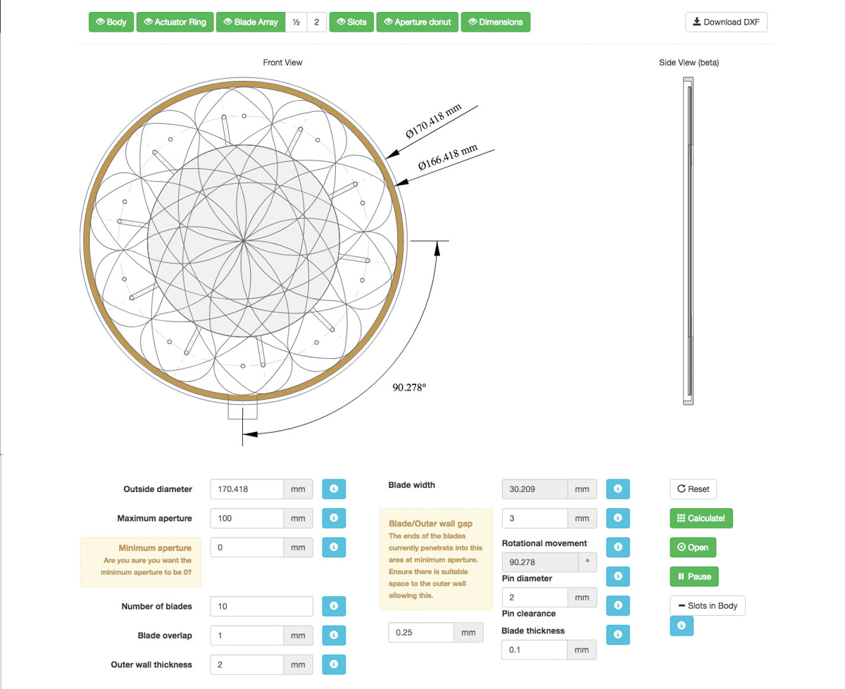
Baptiste found a page that has an iris calculator . It’s an online software tool that helps design and make mechanical iris diaphragm apertures given a set of specifications. This is great because we don’t have to work from scratch and it basically means we have a parametric page to help out if we decide to change the specifications of our project down the line.
Day 3
We’ve divided the tasks, more or less. Baptiste will be gone for the whole week, starting tomorrow, so he’ll be working remotely on the group page for our project, Javi and I will be working on the mechanical design of the iris and Daniel is investigating on the mechanical design of the axis.
Figuring out how the iris work seems simple enough, but we quickly realise that the iris generator we’re using is a bit picky when it comes to the kind of parameters that go into it. It’s not happy with just any set of parameters.
As I start to tinker with it, I manage to make it work and figure out what settings are upsetting the software and why.
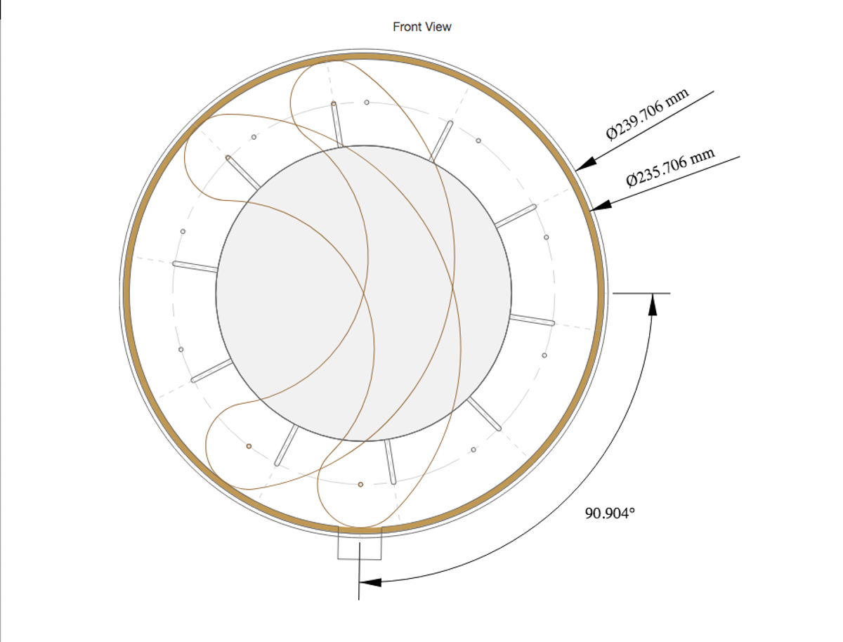
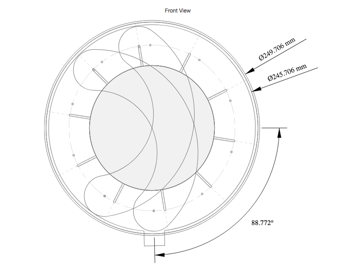
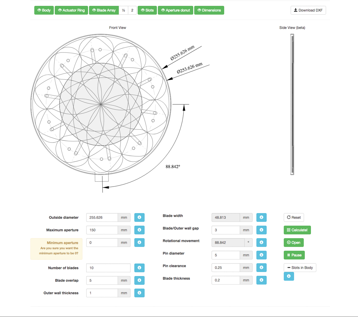
The final design can be downloaded directly from the page as a .DXF file.
The final iris design come out like this.
Turns out the generator works out some dimensions quite well but doesn’t give you a fully done design. It comes out as an exclusively 2D set of layered drawing that more or less constitute the parts of the iris. For are purposes, that is enough, but given that the file offered is .DXF some people might expect a fully solid 3D design, all pieces prepped.
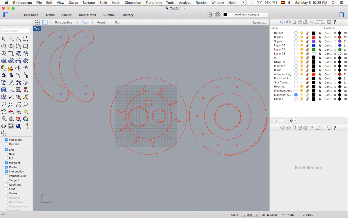
I imported the files to Rhino and started to ready the files to make a quick prototype with the laser cutter.
I finished drawing the rails and made some minor changes in the layering for the cutting, but otherwise the five euros were more or less worth it. It definitely saved some calculating and drawing time.
Javi worked on a gear design to add it to the iris drawing to control the opening with a servo motor.
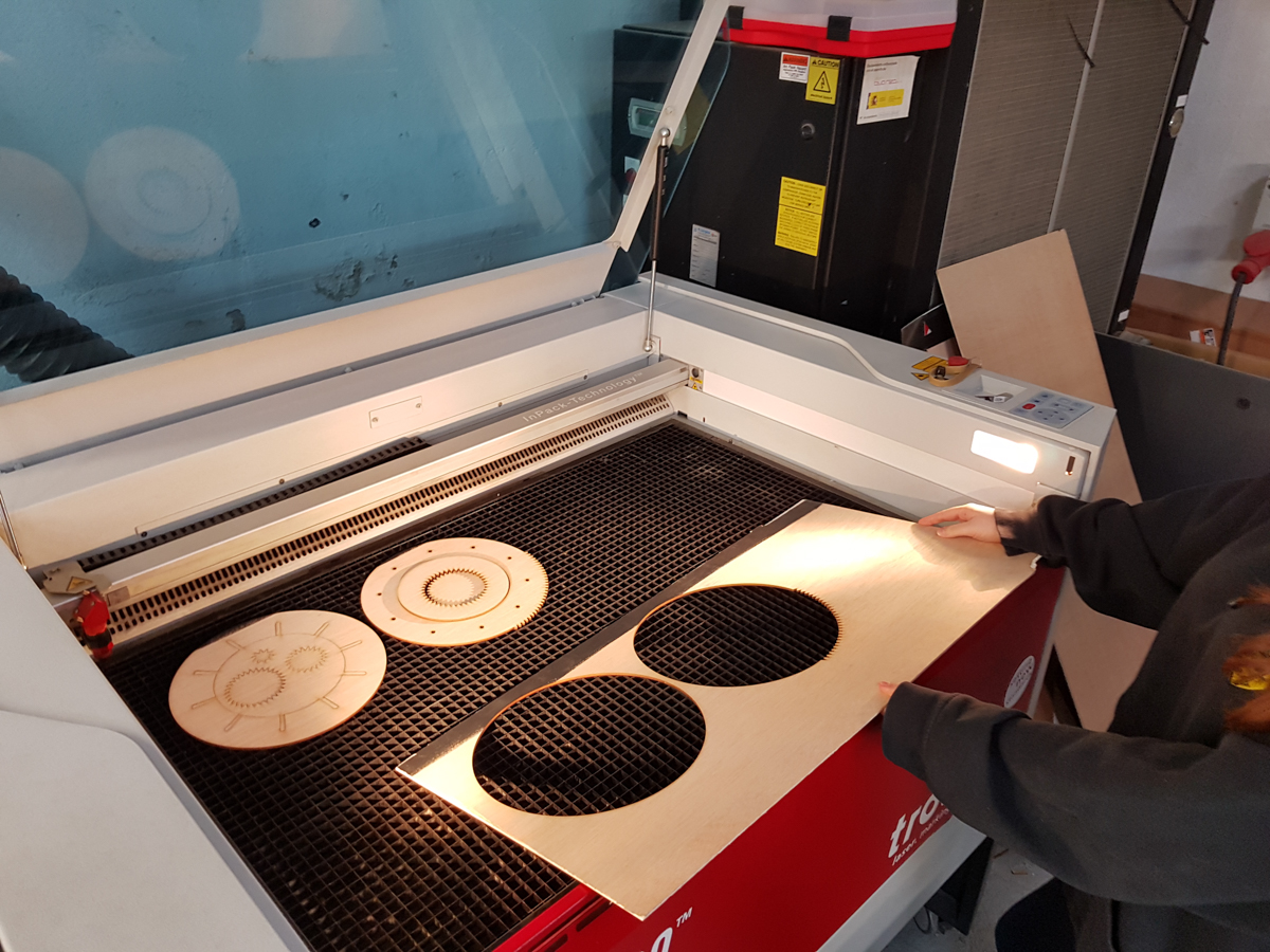
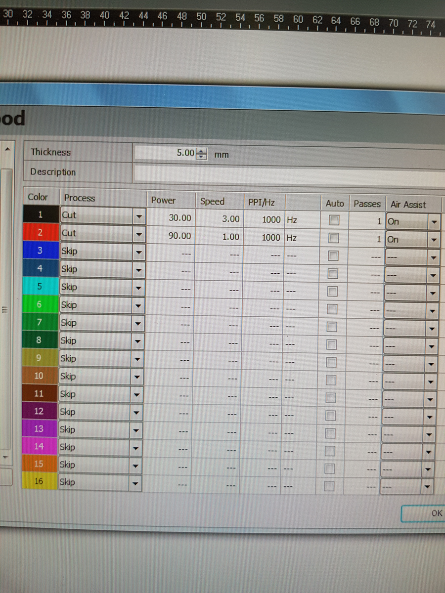
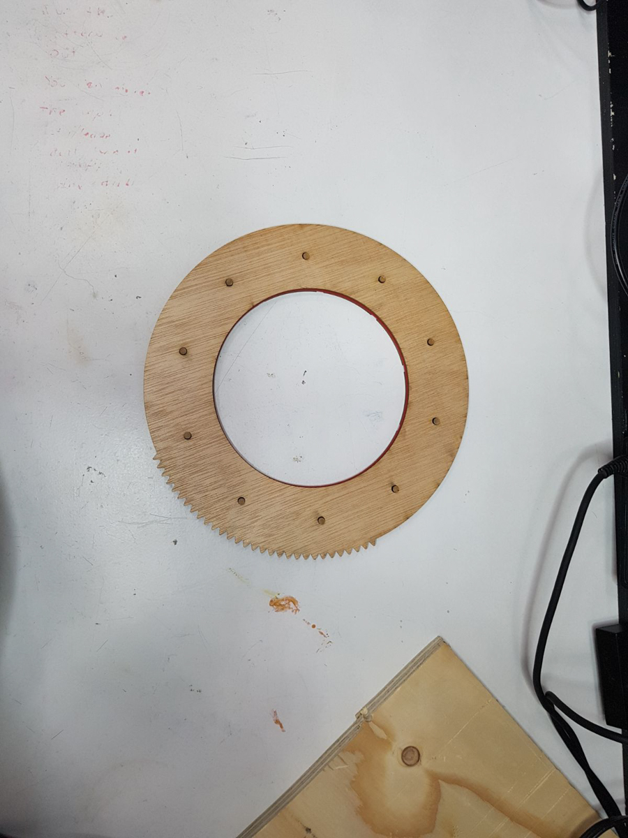
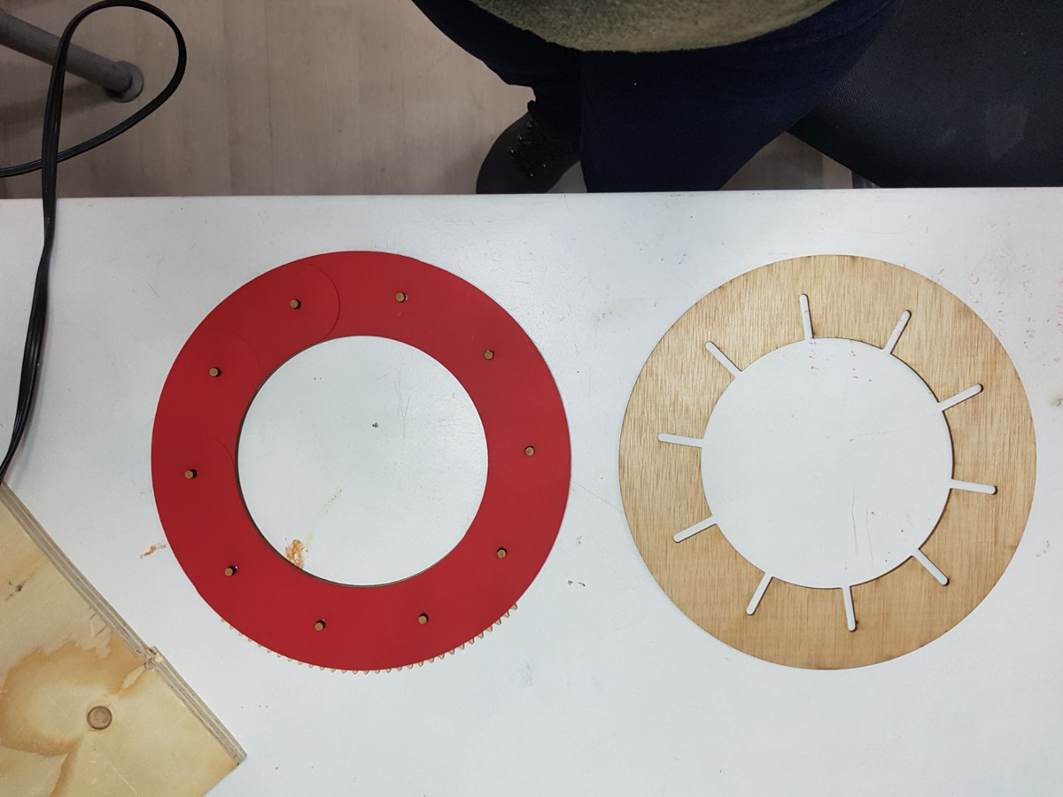
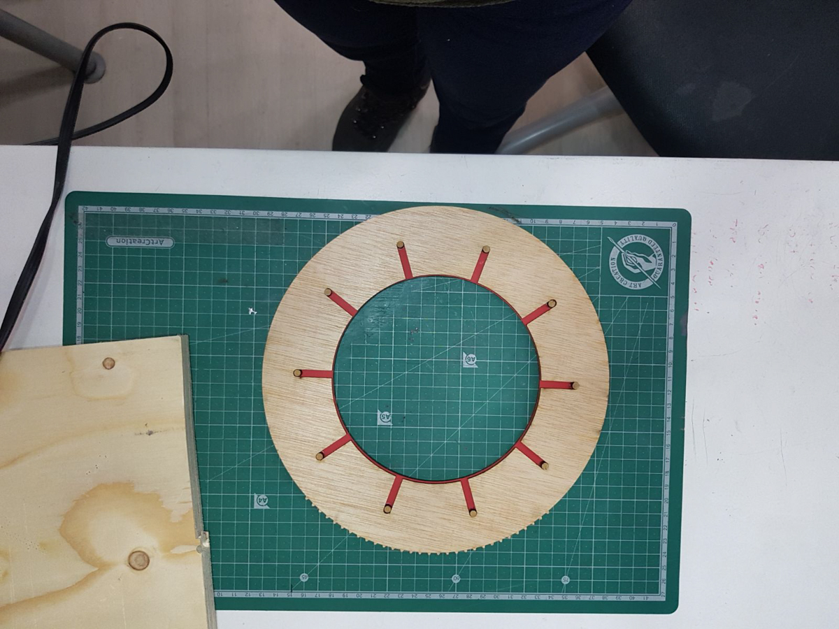
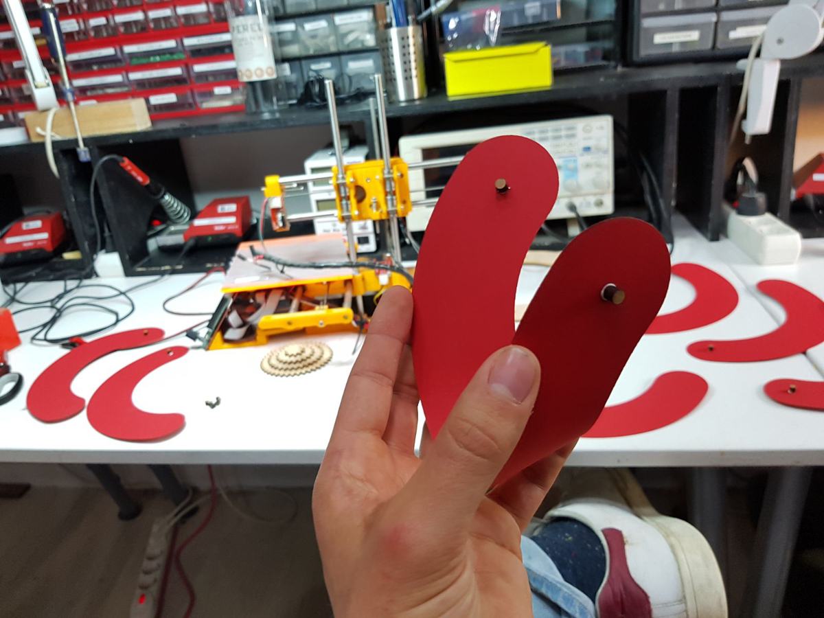
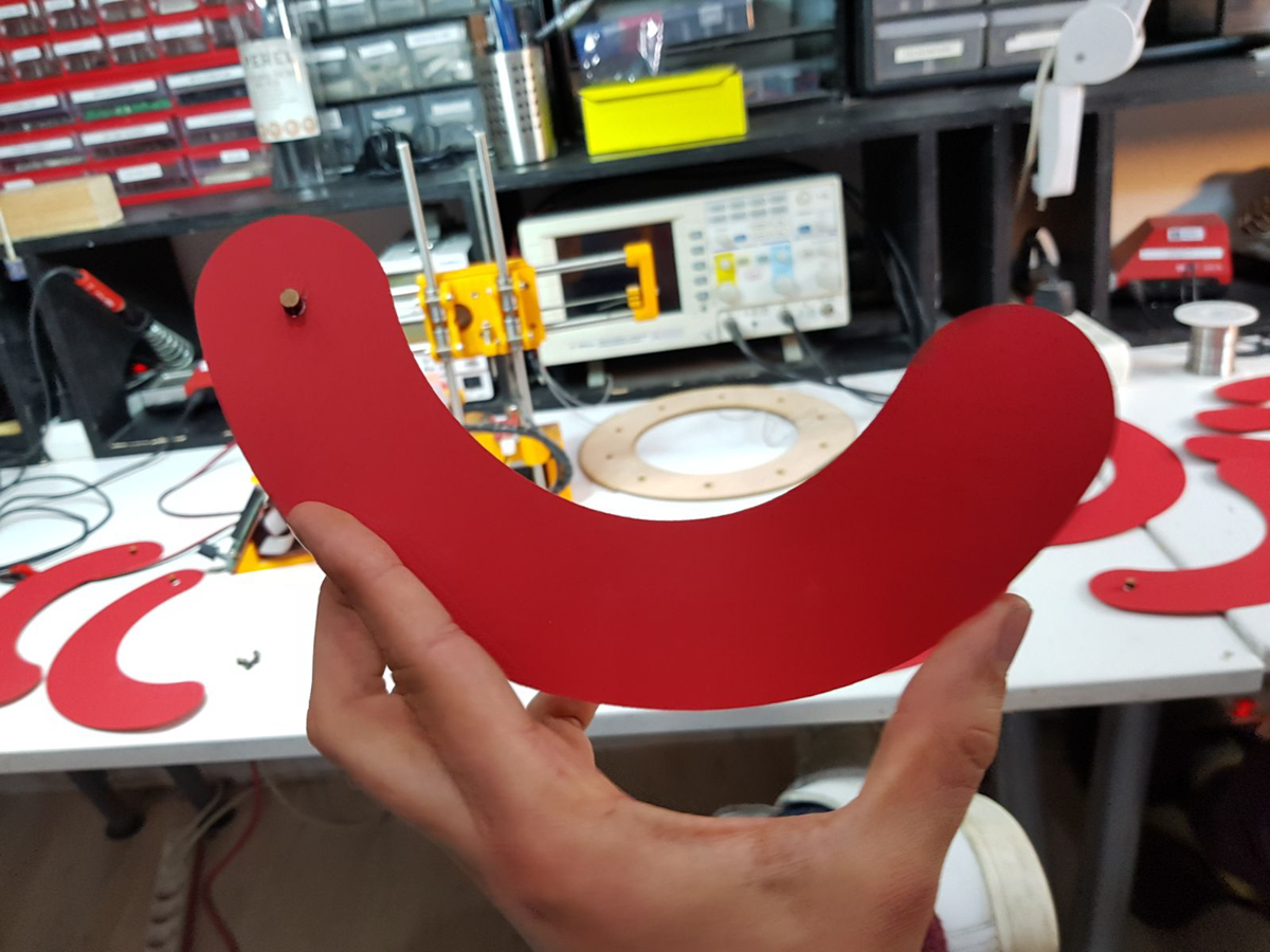
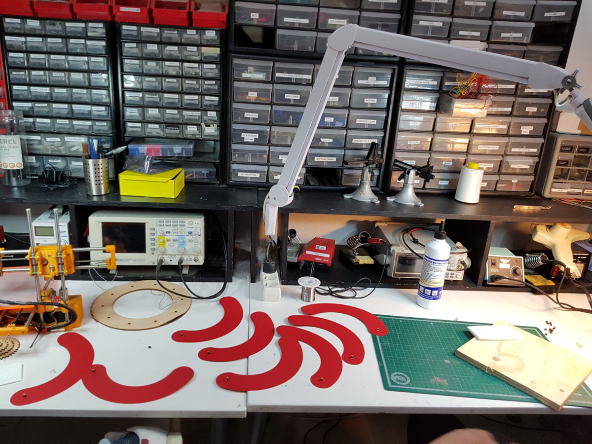
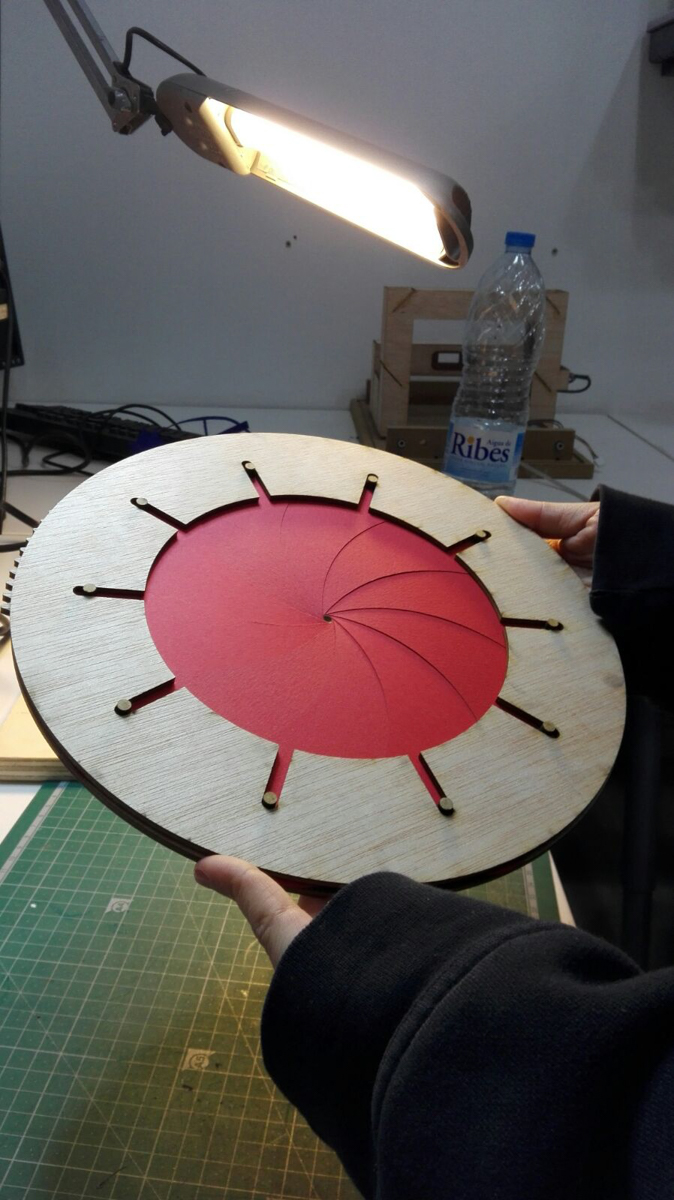
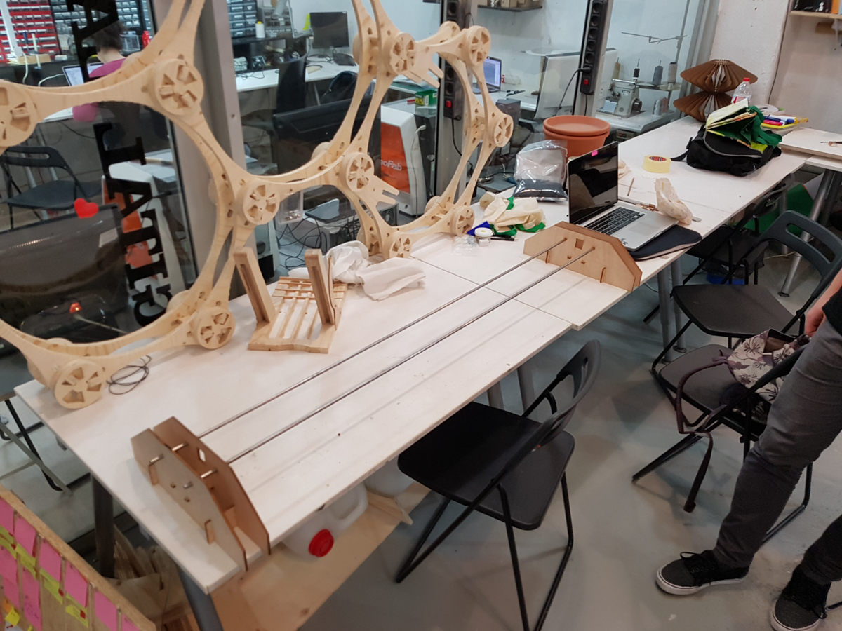
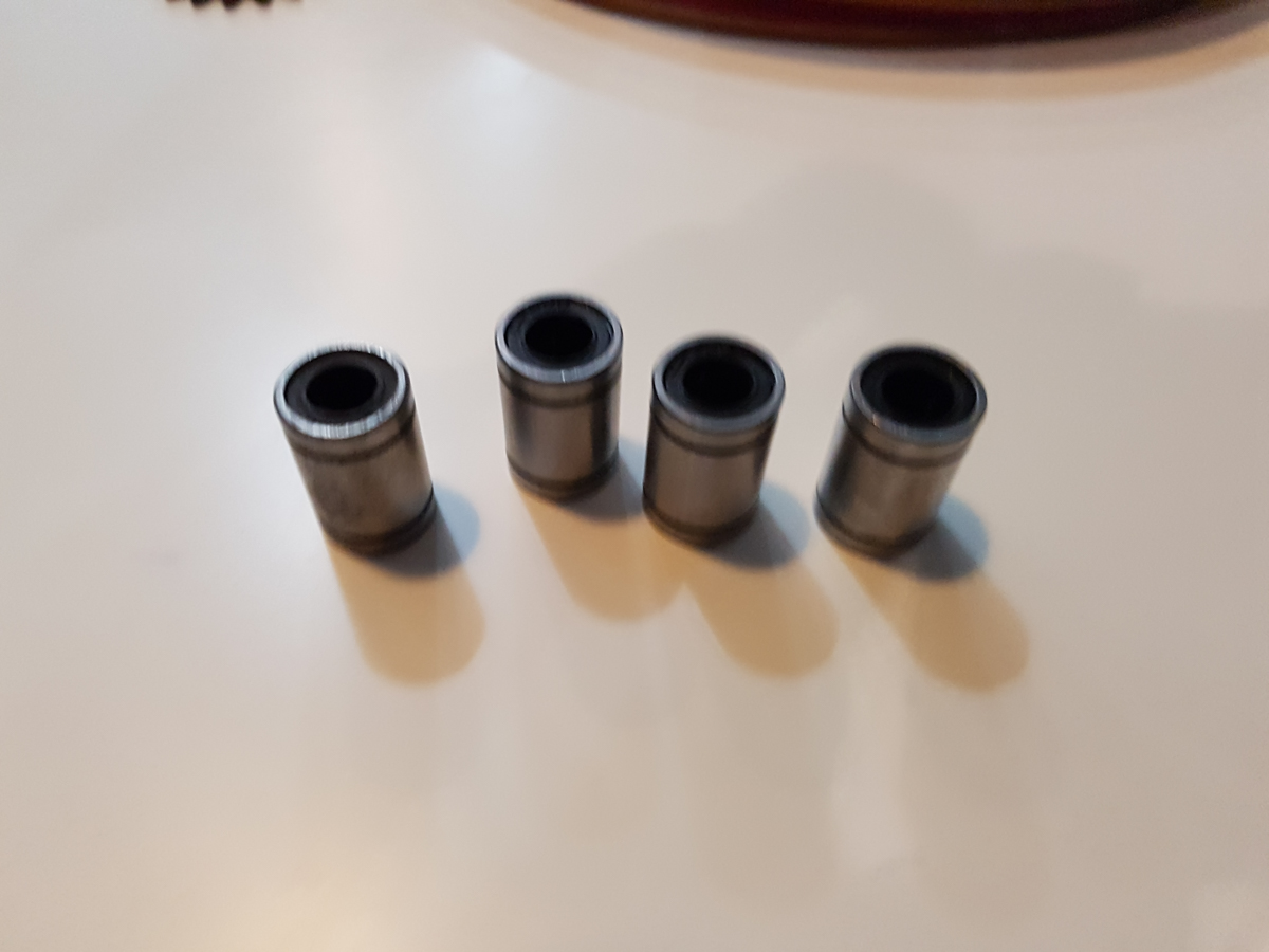
We then cut the design with the laser cutter in raft wood and the leafs in paper cardboard, to get a rough idea of what it would look like and work. We also cut some circles in a 5mm thick mdf, to make the pins that go into the rails where the leafs get their movement, seeing as they don’t have to have any extraordinary height.
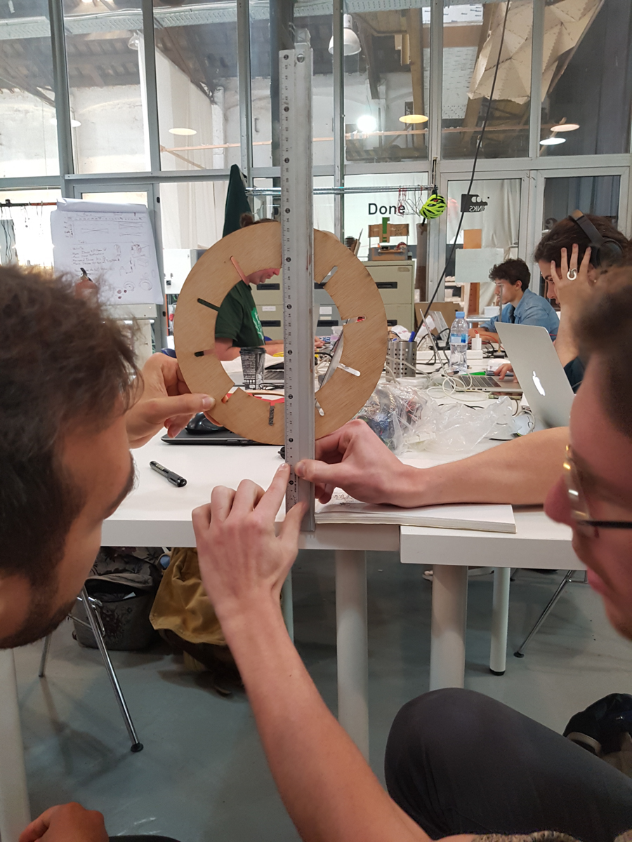
The result was quite good, but we quickly realised we failed to make a frame for the iris so to make it work and keep it in place, I had to hold it in my hand and make the rotation motion.
By the end of the day we’ve created our group page repository and have access to it, Baptiste has a basic page up and we’ve made a first design approach and quick prototype of the iris.
It’s looking good and I’m hoping we have enough time to make a more complicated machine as the week goes on.
Day 5
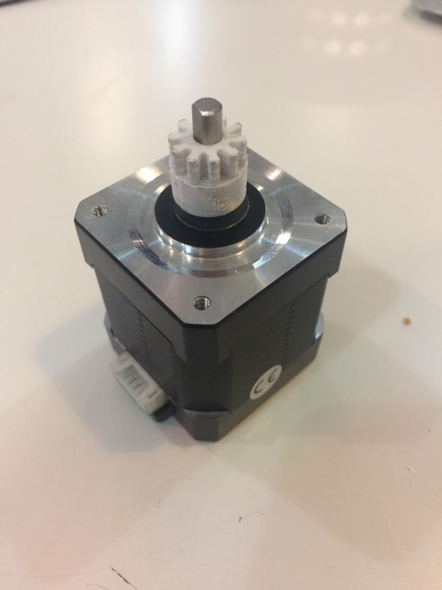
We’ve settled on using a stepper motor to generate the movement, and a belt and a pulley on the other side of the rails to move the iris.
We’ve divided design tasks as far as what we’re refining for the second cut on the laser cutter.
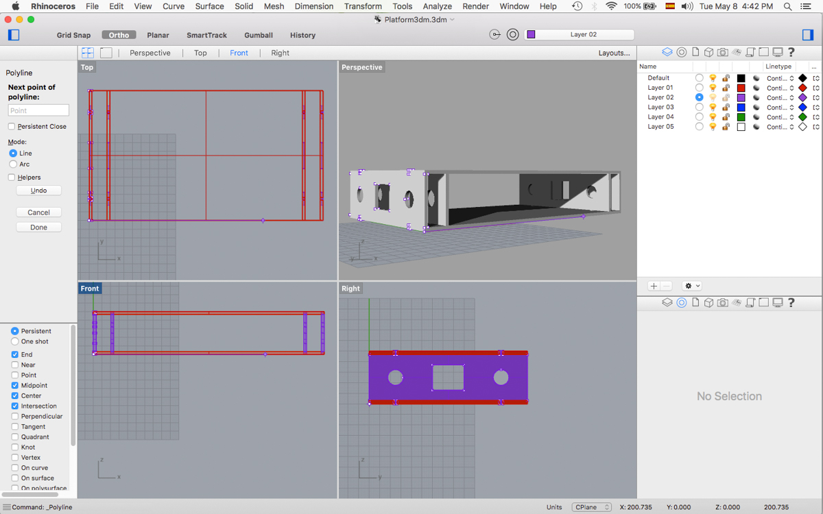
Javi is refining the design of the actual iris, Dan is designing the base for the rails and the motor and I’m designing the platform piece in which Javi’s design will rest.
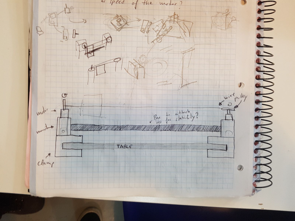
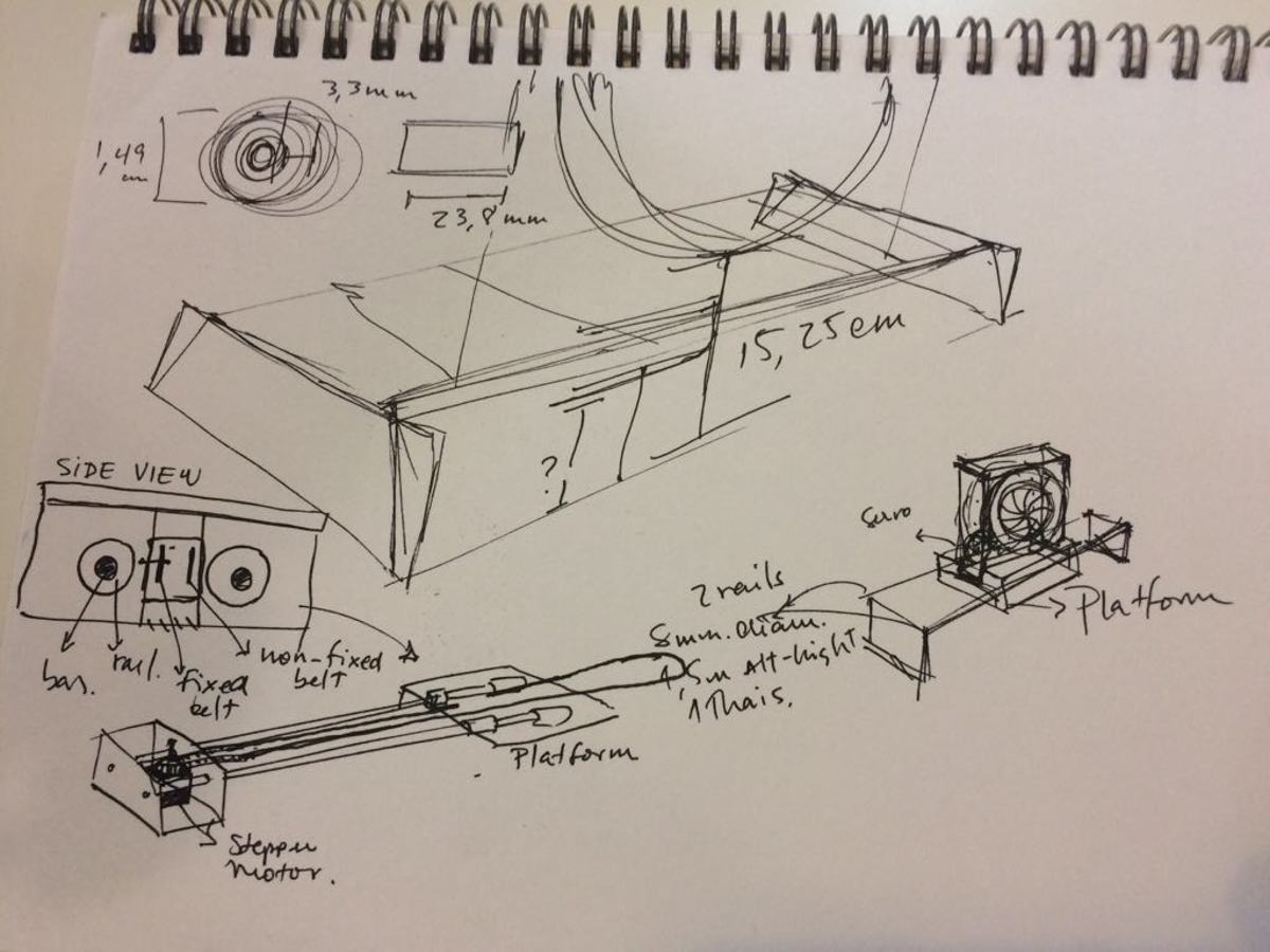
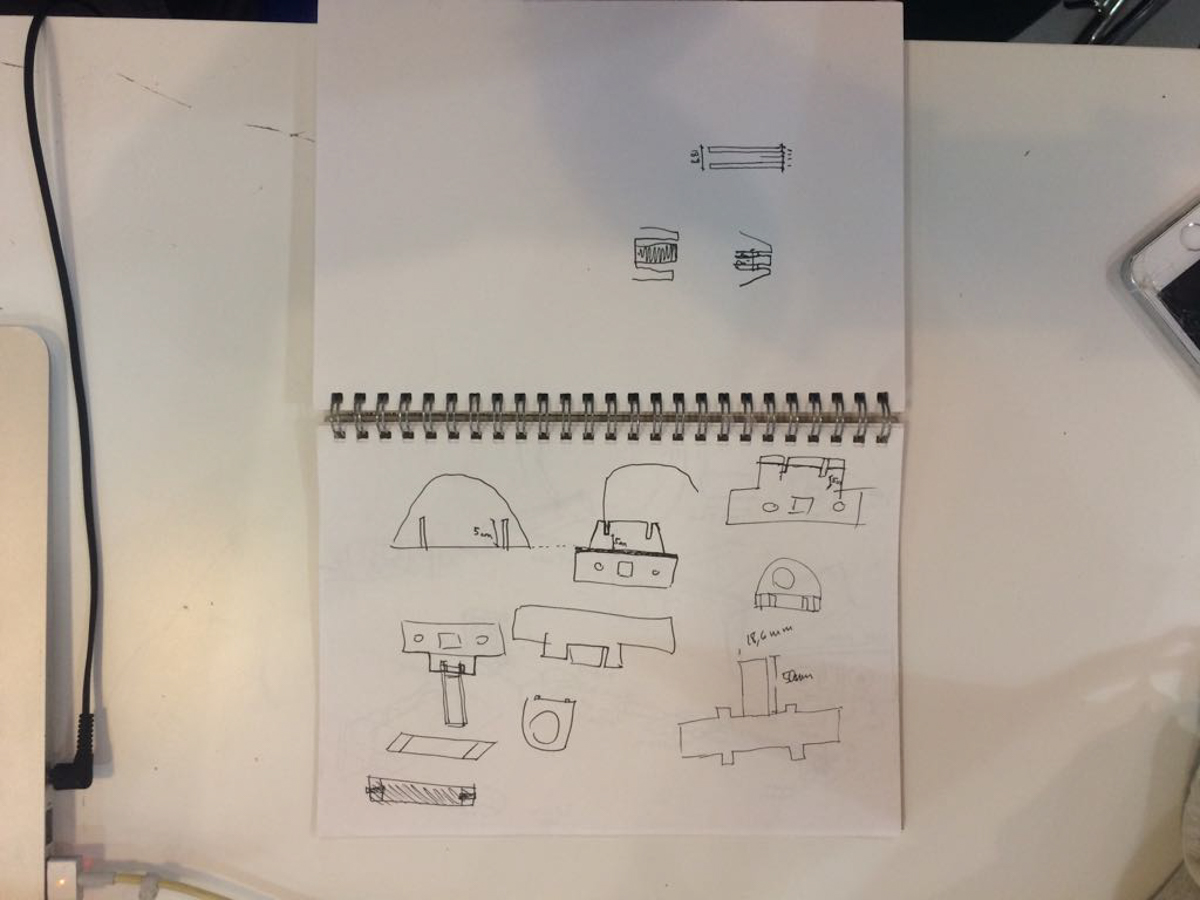
The sketch for the general design looks like this:
We’ve also agreed that we’ll be using plywood for all the construction. It’s sturdy enough and it doesn’t add much weight, which will be important once there’s a motor trying to pull it.
Day 7
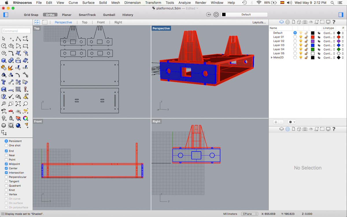
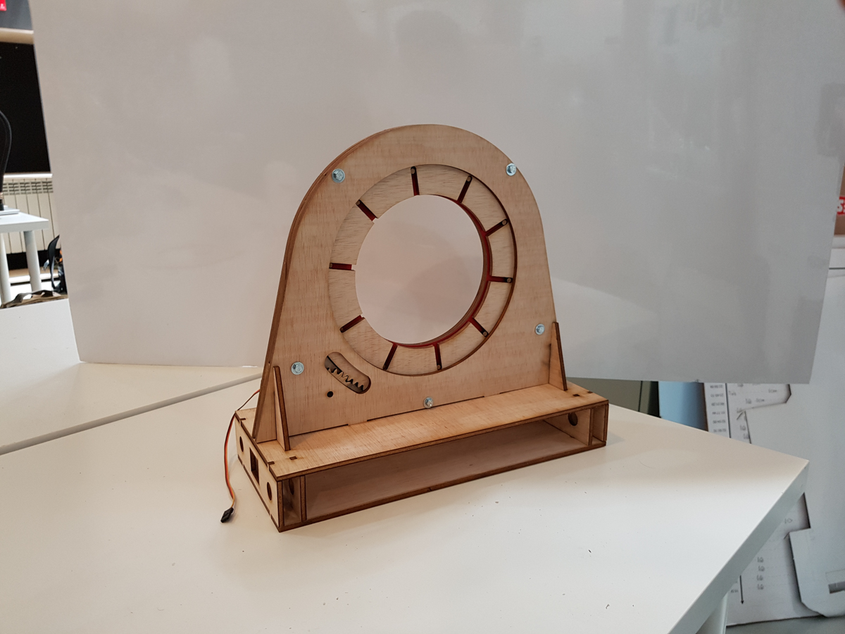
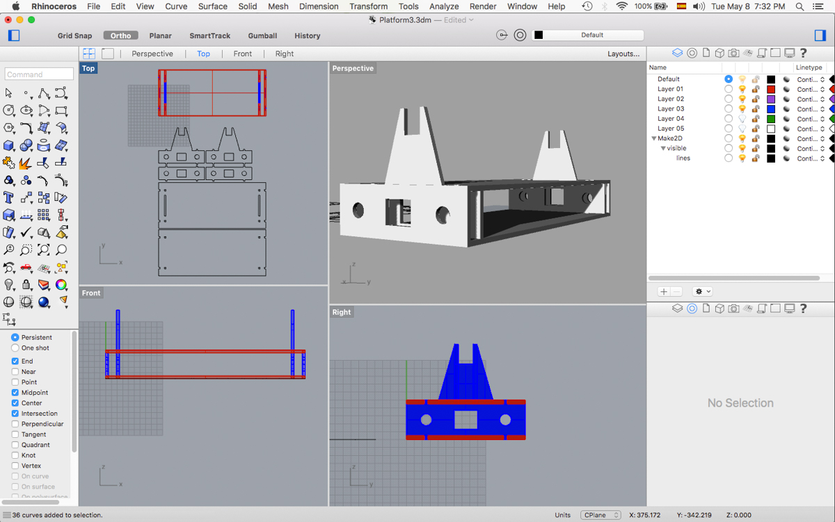
I've finished the platform design in consonance with Javi's design:
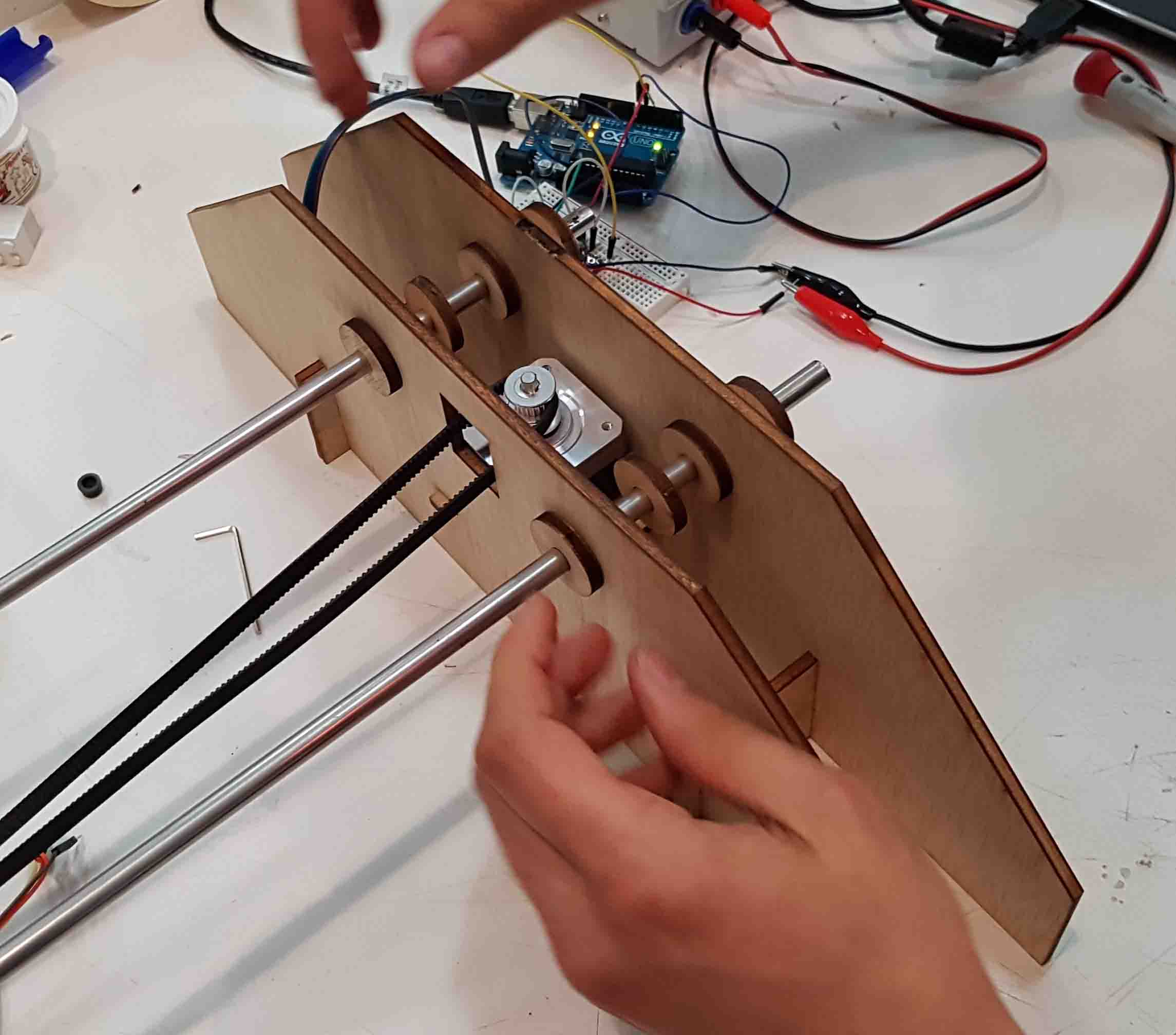
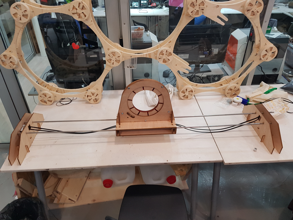
We’ve finished the assembly of the machine, and all that is left is to program the stepper and the servo motors.
Day 8
We’ve refined and recut all the plywood pieces.
The final design files can be downloaded here and here
Day 9
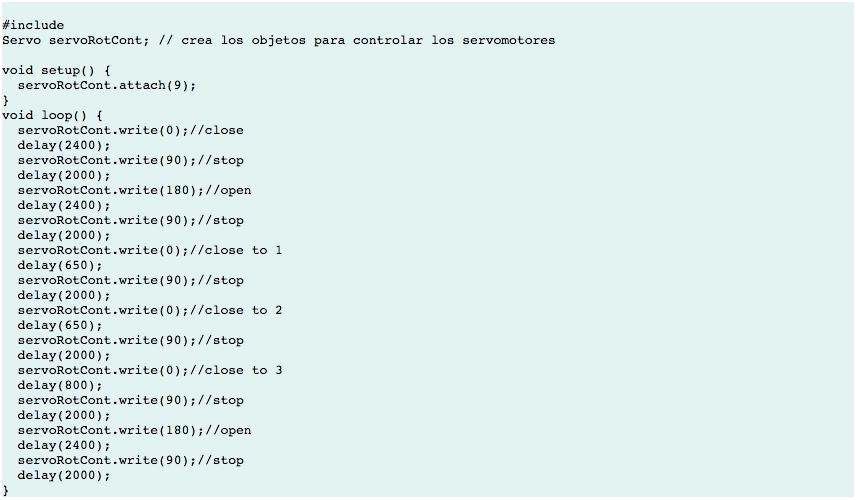
We’ve managed to program the servo to close and open the iris.
The code for it is the following:
Day 12
Programing the Stepper motor was more challenging.
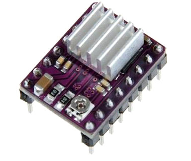
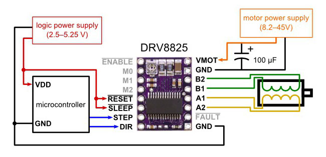
We will use the DRV8825 Stepper Motor Driver Carrier.
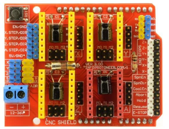
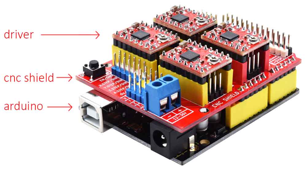
Arduino has a shield compatible with these drivers, the CNC shield:
This shield goes on top of the Arduino board and connects the arduino to the driver, like this:
I tried to follow Andrés’ documentation , which is very detailed, but for some reason all my attempts failed so I asked Javi to step in.
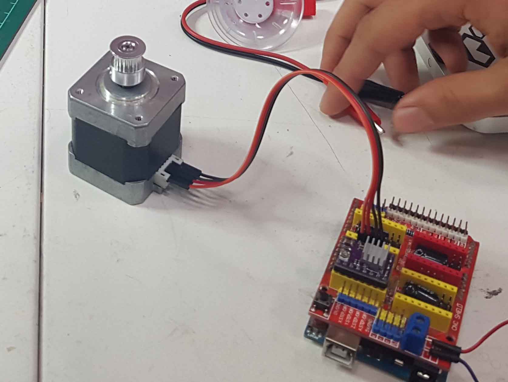
After assembling everything and uploading some code to Arduino, the motor was not working very well. The motor made some noise but it didn't move. Tried rotating the potentiometer in the driver with a screwdriver but the motor still didn't move.
The CNC shield didn’t appear to be working so we made all the connections between Arduino and the driver using jumpers and a protoboard. The good thing about this is that we now understand better the driver pinout.
A1 and A2 (yellow) are connected to one of the coils in the stepper motor (first and third pin). B1 and B2 (green) are connected to the other coil (fourth and sixth pin). There are two pins in the stepper motor that are not used.
This time the motor was still not moving but it made a better sound than before. We struggled a little bit with the code for the stepper motor. Mikel wrote a code to see if it was working correctly. Rotating the potentiometer in the driver made it finally work (the potentiometer is very sensitive, and a very little rotation will make it work or not). Now that we knew everything was working perfectly, we tried to understand the code and write it ourselves.
Our code didn't work...some of the delay functions were in microseconds (delayMicroseconds) when it had to be in milliseconds (delay). Fixing this finally made it work.
For it to work properly the belt needs to be tight, otherwise it will not grab the pulleys correctly.
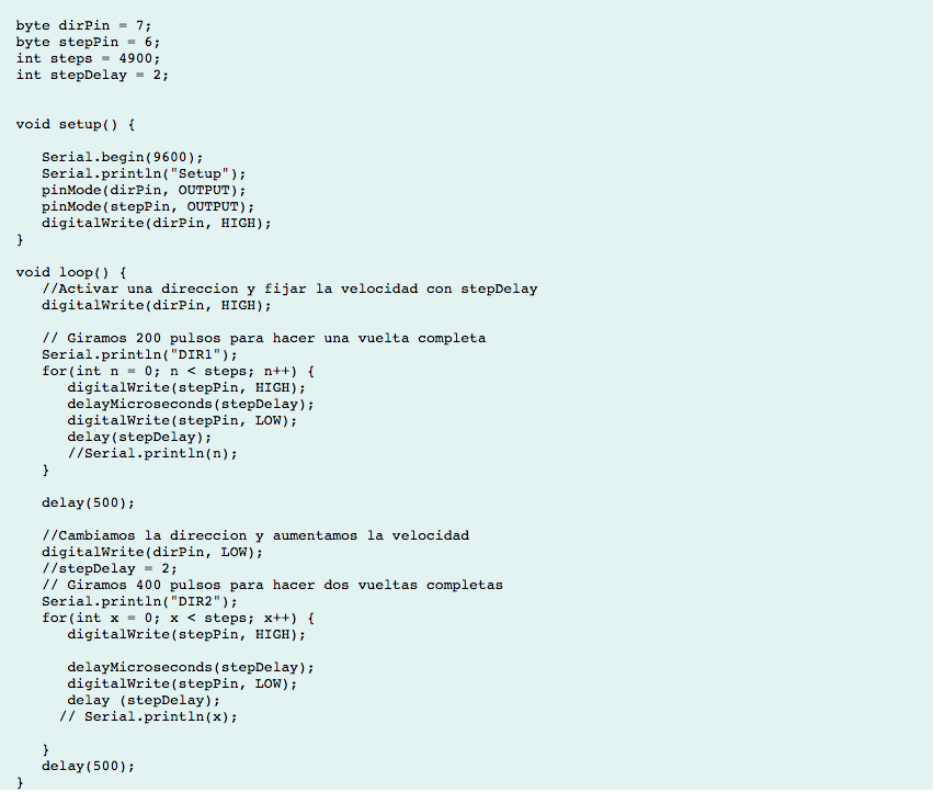
The code we uploaded is a loop to spin the motor one direction and the spin it the same steps on the other direction, so the platform can go from one side to the other side of the machine. To know how many steps it needs we did it by trial. 1000 steps made the platform move around 20%, so we kept increasing this number until it reached the other side. 4900 steps seem ok to move the platform along all the railings.
For more information on the process you can have a look at our group page.

.jpg)