Design a microcontroller board and have it read a sensor. Really?
I barely understood what I made last electronics assignment.
So, all the things that were described were amazing, but I’ve not the foggiest on how to make any of it. Most of the class went over my head. I’m going to have to watch it again if I’m going to get anything done this week. .
Neil just clarified the last minute of the class that he’s not looking for us to do everything from scratch but rather we can work from his board as a starting point, which is an immense relief.
Day 2
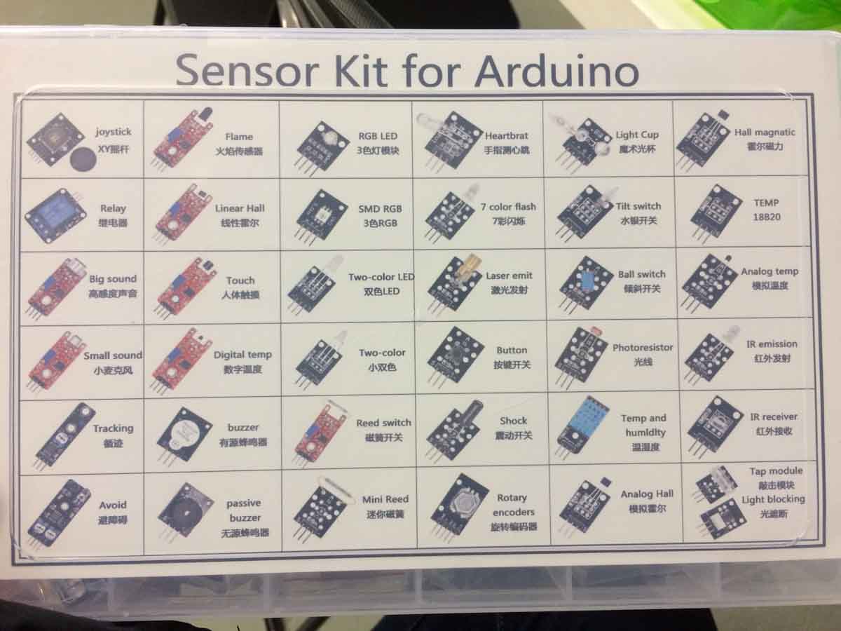
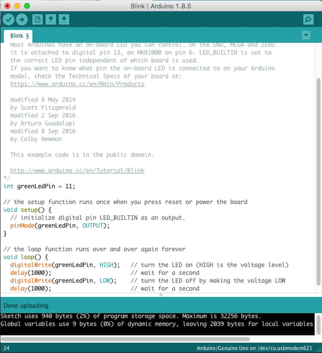
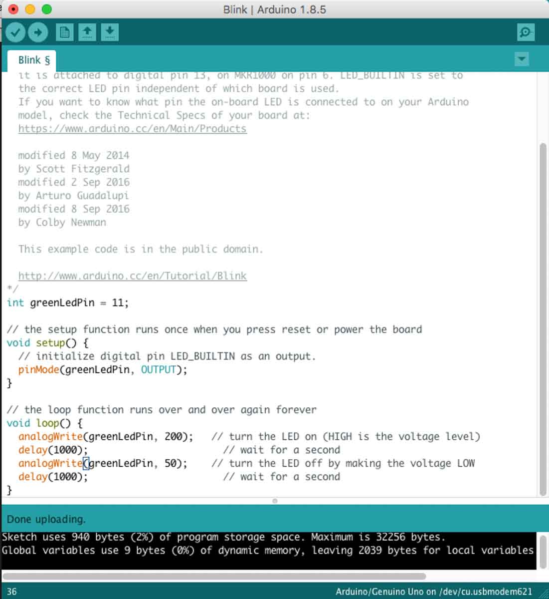
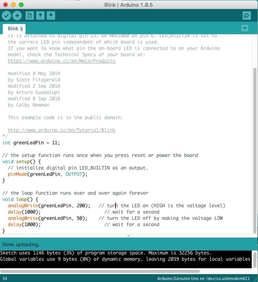
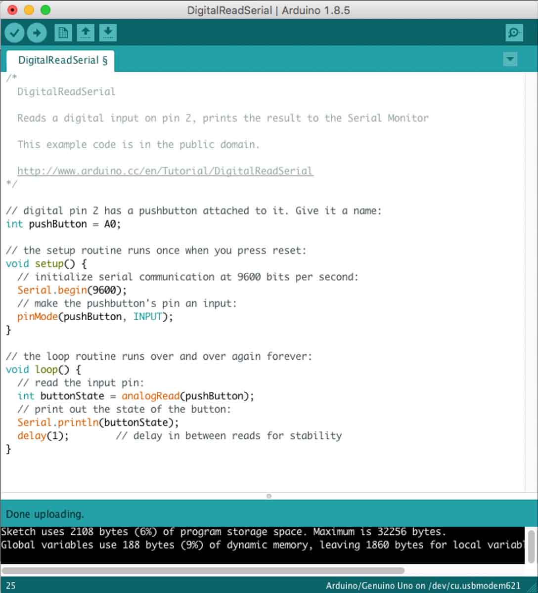
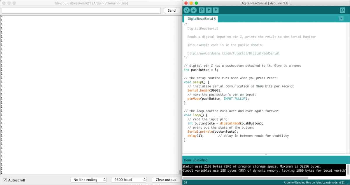
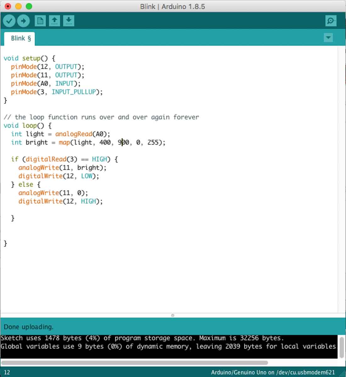
So, before getting to the design, I thought I’d try out the sensors I wanted to use with an Arduino Uno, to see how they worked, etc.
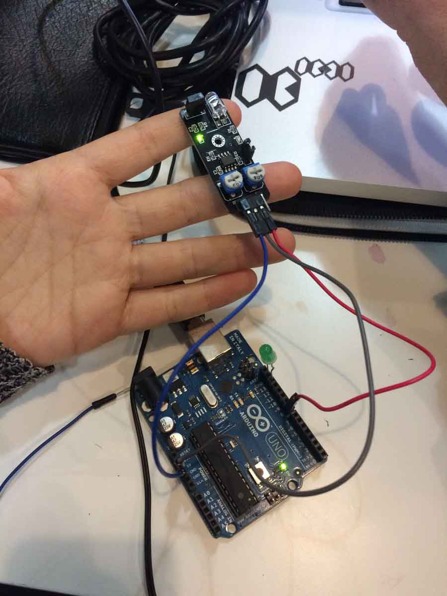
My first attempt was to program the Avoid sensor from the Sensor Kit for Arduino.
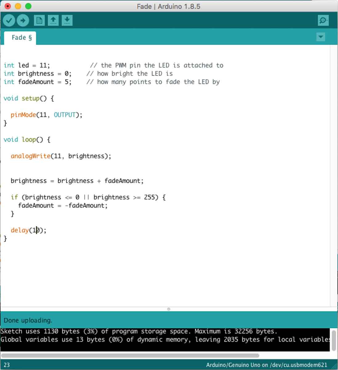
That sensor has a IR emitter and receiver in a prebuilt board. What I wanted was to use it to measure distance, granted, of a very limited range.
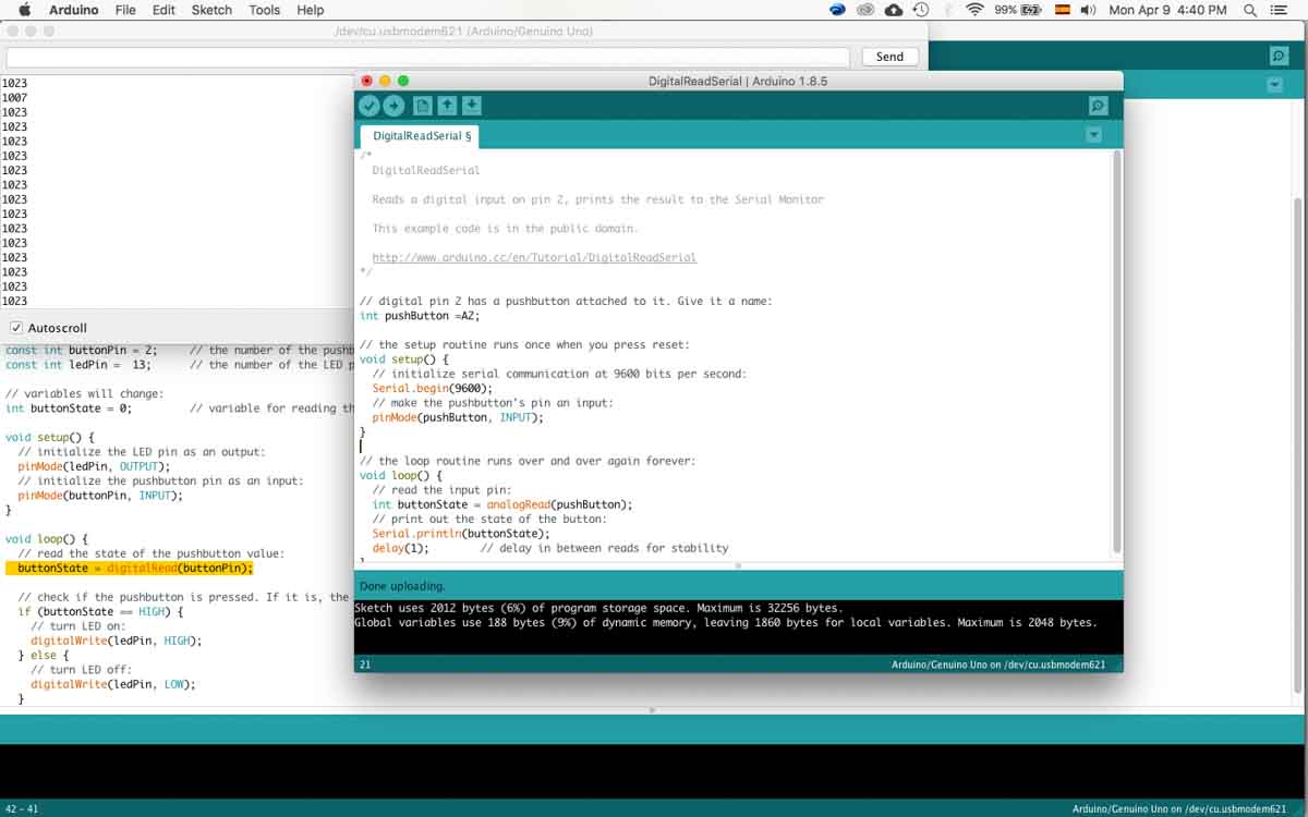
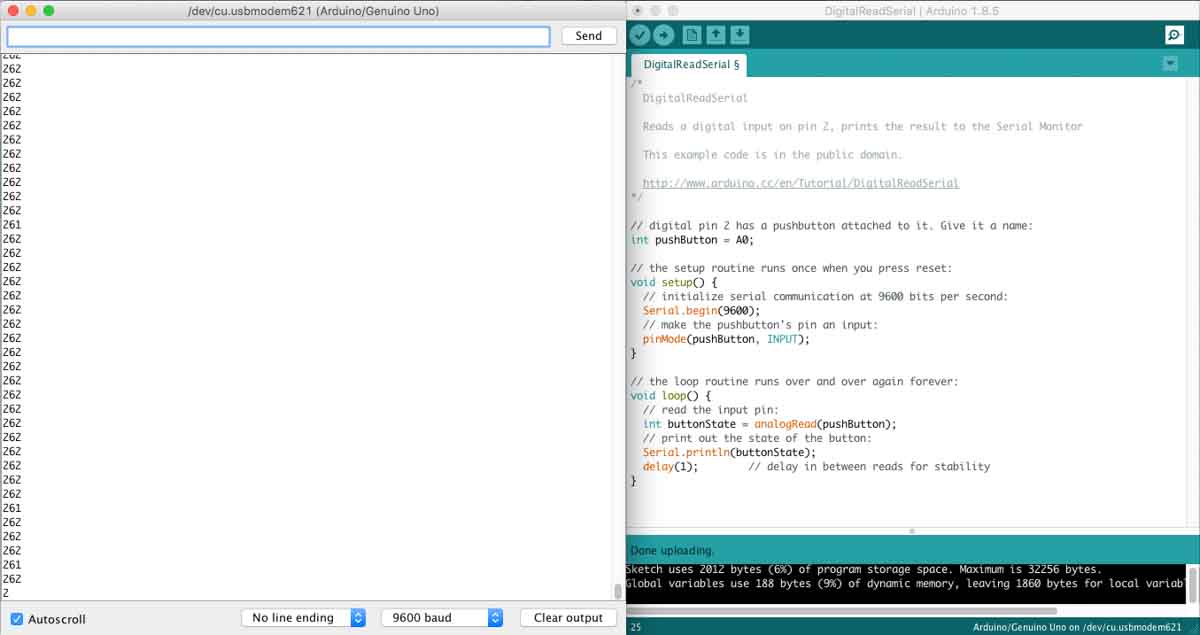
But for some reason there was a reading of some kind bu it remained static, no matter what example protocol we tried, with different modifications, of course.
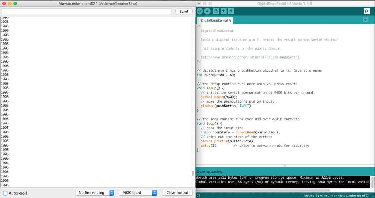
I then tried IR emission sensor and the IR receiver with a breadboard and again, the results, where we got any, weren’t true readings.
However, even with the help of the instructors I still couldn’t manage to get it to work properly, at least for the purpose of measuring distance.
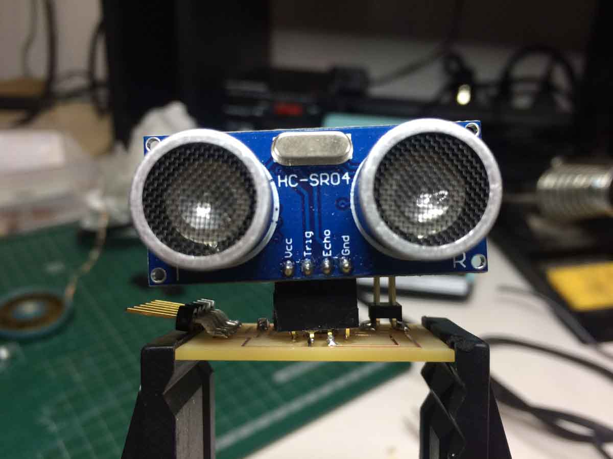
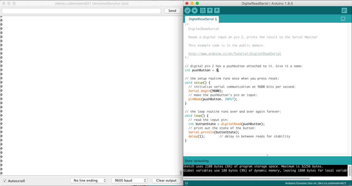
I ended up trying the Sonar sensor, which I was slightly reluctant to use.
What I had envisioned was recreating a single module, or a smaller scale module that was done on the following video:
And possibly do something like this for my final project:
Now, it became quickly apparent that I wouldn’t have the resources to make something like that, but still I wanted to use sensors that might sense proximity with analog pins, as opposed to digital pin.
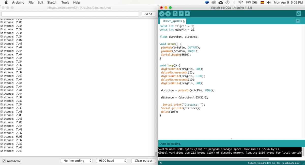
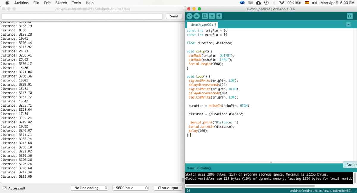
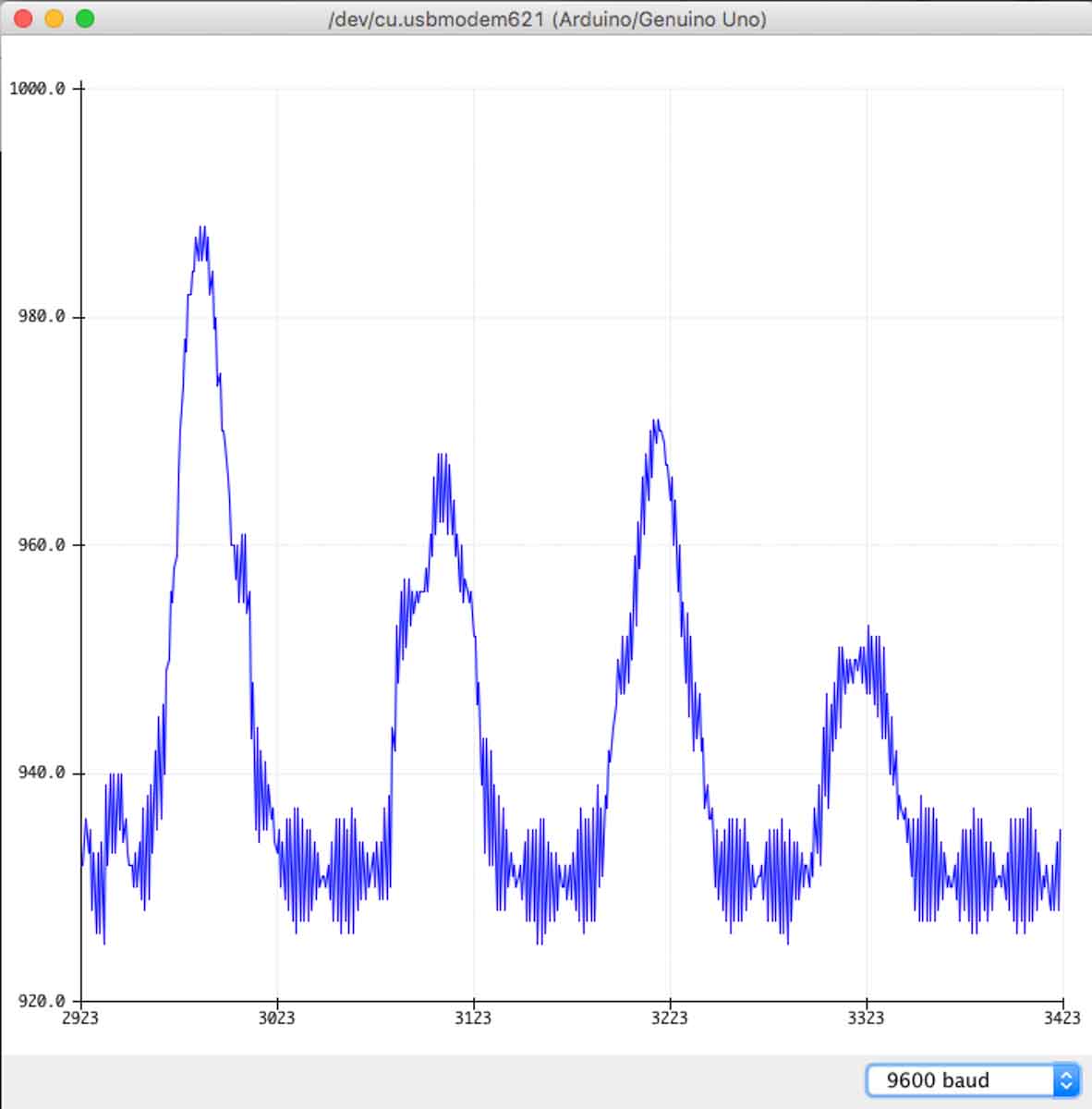
The sonar sensor finally worked and had coherent readings, but the reason I was reluctant to use it, and Neil mentioned it during the class, it only works properly when the object is flat and is approaching the sensor in a parallel motion towards it. If the flat object is not parallel to the sensor, it goes a little crazy and has big jumps in it’s readings because it reads the closest part of the object and the furthest one at the same time.
This was the result when using a flat object, parallel to the sensor.
This was the result when using an irregular object.
Day 5
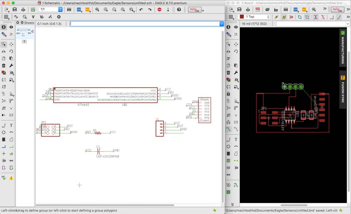
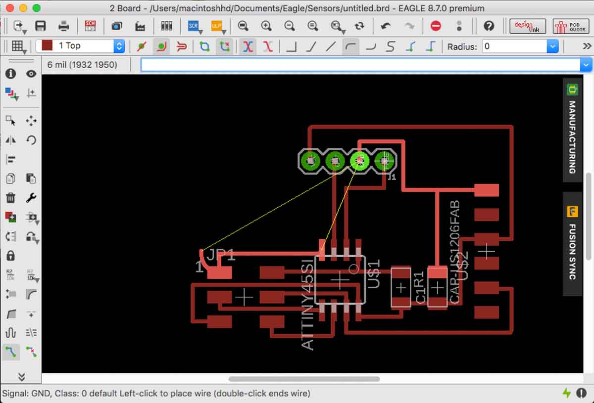
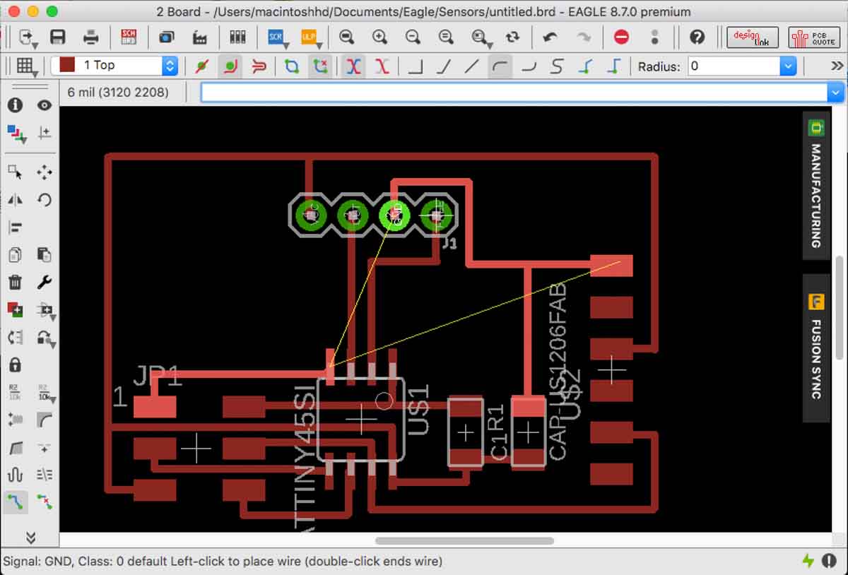
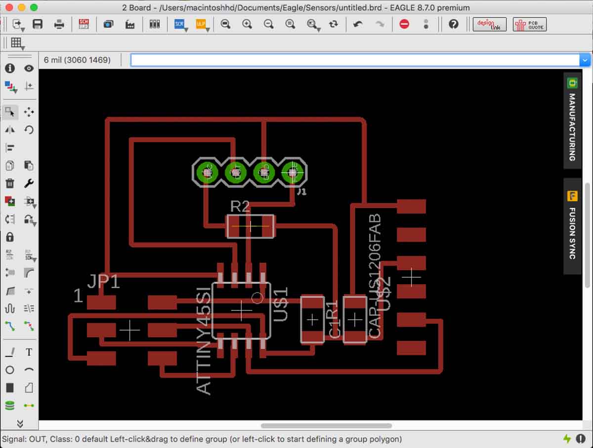
I settled with the sonar but didn’t give up completely. I decided to modify the board supplied by Neil to be able to connect other sensors to the same board by putting a female pin header where the sonar sensor should be. By adding another entry point and connecting it with the free pin left in the ATTinny45, with a small shield I should be able to use the same board by connecting it to the shield and whatever sensor has either the same three entry points or a sensor that requires four, and the shield would connect the VCC, out and ground respectively in the proper order. I could even connect another sensor without the shield if the order of the pins of the sensor are the same as the ones in the board.
In any case, I had to also add a resistor 0, as a connecting bridge, to finish the design because some either the GND or the VCC would close off the path for the other.
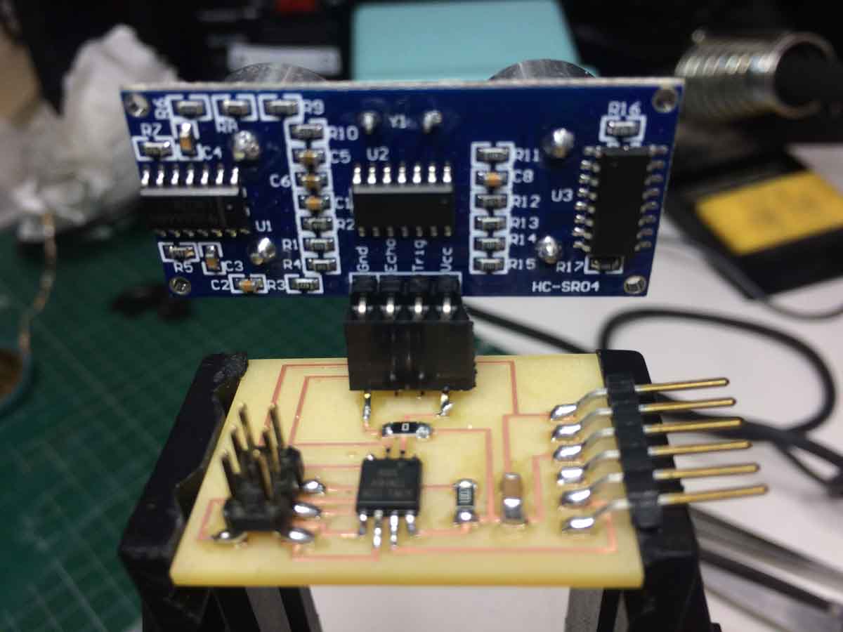
However, since the original design was meant for a different sensor, when I modified it for the female header, I forgot to reorder the connections for the sonar and so when I plugged it in the computer it was shorting and the sensor got really hot and burned my hand. Initially I didn’t know why this was happening until I had a second look at the schematics.
I had to use jumper cables to connect it properly, but it worked out properly and I was able to program the board and make it work without a problem in the FabLab computer.