Week 8 - Embedded programming
Assignment
Read a microcontroller data sheet.
Program your board to do something, with as many different programming languages and programming environments as possible
Optionally, experiment with other architectures
This week we are programming the board we made in the week 6 assignment to make the Led flash
Reading Data sheet
I must say that the reading of the Datasheet is somewhat long and cumbersome, I kept reading and understanding but this is very long 286 pages!
ATtiny 44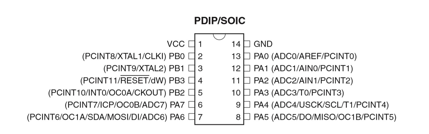
I must say that the reading of the Datasheet is somewhat long and cumbersome, I kept reading and understanding but this is very long 286 pages!
Before say something about the ATtiny45 we should kknow the difference between "microcontroller and micropocessor
A microcontroller is a small computer on a single integrated circuit. In modern terminology, it is similar to, but less sophisticated than, a system on a chip or SoC; an SoC may include a microcontroller as one of its components. A microcontroller contains one or more CPUs (processor cores) along with memory and programmable input/output peripherals. Program memory in the form of ferroelectric RAM, NOR flash or OTP ROM is also often included on chip, as well as a small amount of RAM. Microcontrollers are designed for embedded applications, in contrast to the microprocessors used in personal computers or other general purpose applications consisting of various discrete chips.
A microprocessor is a computer processor that incorporates the functions of a central processing unit on a single integrated circuit (IC),[1] or at most a few integrated circuits.[2] The microprocessor is a multipurpose, clock driven, register based, digital-integrated circuit that accepts binary data as input, processes it according to instructions stored in its memory, and provides results as output. Microprocessors contain both combinational logic and sequential digital logic. Microprocessors operate on numbers and symbols represented in the binary numeral system.
From what I have read thoroughly and what I have scanned I can highlight the following data of interest:
- The ATtiny44 is a 8 bit microcontroller with possible 2K, 4K or 8K Flash program memory and 128, 256 or 512 Bytes of In-System Programmable EEPROM
-The operating voltagle is between 1.8 to 5.5v. This means that I can use a 5v power source which always good to know.
The table 10.3 on page 60 is important to know what are the alternate functions of each pin.
- "I/O" = Input/Output
Programming
Before starting, it is convenient to follow this FabAcademy tutorial
I will try to make the programming on C a great challenge for me, I'm more of Making things, an Atoms guy.
In a previous assignment I had problems with windows 10, so I decided to install Ubuntu on my computer, I also downloaded GCC compiler, I'll use it again
Download GCC.
We also better install the AVR Libc package, it provides a subset of the standard C library for Atmel AVR 8-bit RISC microcontrollers.ATtiny 44 is a 8-bit microcontroller. more info Here.
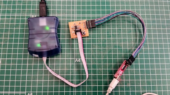
FTDI adapter
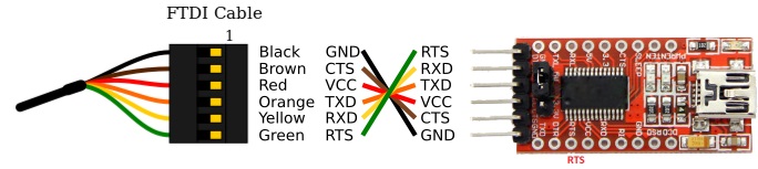
A FTDI cable is needed to this assignment (USB to UART) I decided to buy a converter is less expensive.
Ready to start coding
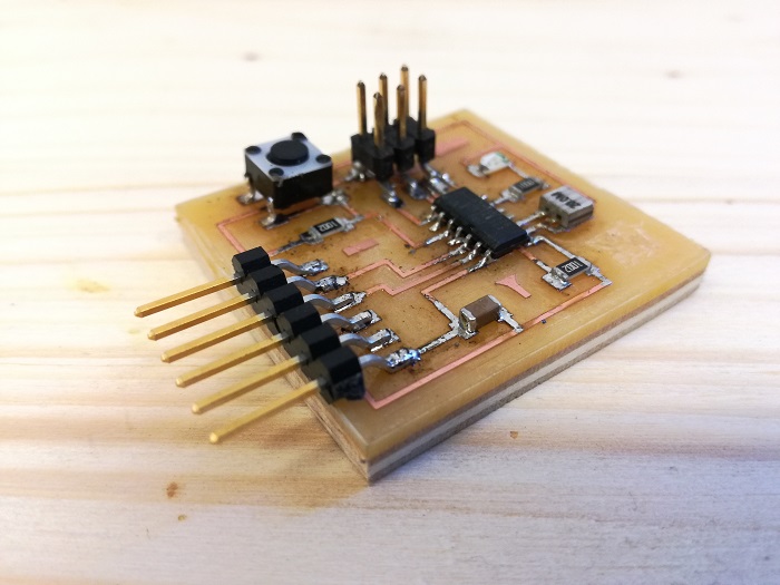
In this assignment we use the board designed and produced in the "Electronic design" assignment. The idea is to reproduce the "blink" example to make a led blink.
This is the code based on Xavi Dominguez Embebed Programming assignment, he is an ex colleague in FabAcademy 2016 and now Instructor in Fab Lab BCN. He tooks Neil's code as example to do his assignment. I'm not going to modify Xavi's code, i'm centered on understanding it.
//
				/**
 * FabAcademy 2016-2018 - Javier Hernandez
 * Thanks Xavi Dominguez
 * * Embeded Programming: Blinking LED
 * * file: main.c
 * created: 2018-03-08
 **/

#include avr/io.h
#include util/delay.h


// Define the I/O port to be used for the LED.
// This a number between 0 and 7 that tells which bit to use.
// View in Datasheet

#define LED_PORT PA7


int main(void) {

    // Set the LED port number as output.
    // The DDRA is the data direction for port A.

    DDRA |= (1 << LED_PORT); // LED PORT AS OUTPUT

    // Start infinite loop.

    while (1) {

        // Set the LED bit to "1" - LED will be "on".

        PORTA |= (1 << LED_PORT);

        // Wait a little.
        // The delay function simply does N-number of "empty" loops.

        _delay_ms(200);

        // Set the LED bit to "0" - LED will be "off".

        PORTA &= ~(1 << LED_PORT);

        // Wait a little.

        _delay_ms(400);

        // Do it again ...
    }

    // Return the mandatory for the "main" function value.
    return (0);
The avr/io.h is used for controlling I/O ports on an AVR microcontroller. If your want to know more about ports on AVR read the datasheet or this great tutorial
First of all, we must include some useful headers to our c code, which are avr/io.h and util/delay.h. The first one is used to include the apropiate Input/Output definitions and their respective bits value for the microcontroller we are using. On the other hand, the header util/delay.h includes some busy-wait functions that allow us to create delays specifying actual time values rahter than a number of cycles to wait for.
Once we have included all necessary headers, we proceed to define the I/O port to be used for the LED, which is, in our case, the PA7 port.
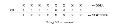
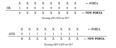
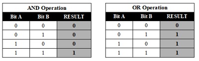
After that, we enter in the main function, where we have to set the LED port number as an output. For this reason, we use the DDRA register, that controls what pins are outputs (1) and what pins are inputs (0). In our case, we need to set PA7 port as an output, and that's why we apply an OR operation between DDRA and a 1 rotated X positions to the left as the number of the port we are using (1000 0000). Once we have done this operation, the bit 7 of the DDRA register is forced to 1, which means that we have set the PA7 port as an output finally.
The while (1) instructions creates an infinite loop, where we will be able to turn on and turn off our LED. In order to achieve this aim, we use the PORTA register to control the voltage levels for each pin ( 0-->0V 1-->5V). As well as we have done with the DDRA register, we apply an OR operation between PORTA and a 1 rotated as positions to the left as the used port number (1000 0000) to set its pertinent bit to 1 in the PORTA register and turn on our LED. But if we want to turn it off, we need to set the bit corresponding to our port to 0. For this reason, we rotate a 1 so many positions to the left as the number of the used port (1000 0000), we complement it (0111 1111) and we apply an AND operation between this byte and the PORTA register. As we can see, between turning on and turning off our LED we need some delays to be able to appreciate this changes.
Finally, we return the mandatory for the “main” function value to show that our program has satisfactorily concluded. In case that our program has some kind of error, we will return anything different from 0.
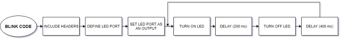
I have tried to explain as much as possible with the knowledge that he can acquire in such a short time, the following diagram may help a little more.
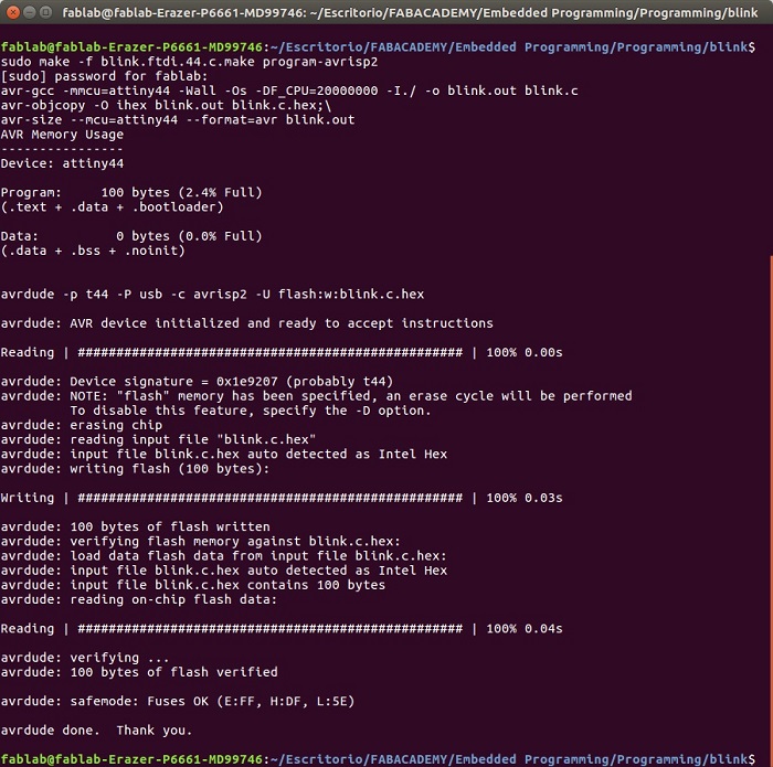
In the first four lines we can see the Name of the file to compile: blink; the Extension of the file to compile: .c ; the Microcontroller to program: attiny44; and Frequency of the board to program: 20000000
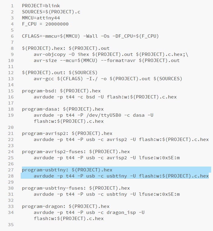
Highlighted in blue the line to be executed
Now it's time to make 'sudo make -f blink.ftdi.44.c.make program-usbtiny'
After testing Xavi's code I made a new one changing the secuence of the led's blink. If you try it you will see that it will blink at a certain speed 8 times and then remains on during 2 seconds. After that the led turns off during 1 second and then it blinks at a higher speed.
This is the code
//
				 * FabAcademy 2018 - Javier Hernandez
 *
 * Embeded Programming: Blinking LED modified
 *
 * file: main.c
 * created: 2018-06-27
 *
 **/

#include
#include

#define LED_PORT PA7


int main(void)
{

    DDRA |= (1 << LED_PORT);

    while (1)
	{
		for (int i=0; i<8; i++;
		{
			PORTA |= (1 << LED_PORT);

			 _delay_ms(200);

			PORTA &= ~(1 << LED_PORT);

			_delay_ms(400);
		}

        PORTA |= (1 << LED_PORT);

        _delay_ms(2000);


		PORTA &= ~(1 << LED_PORT);

        _delay_ms(1000);

        for (int j=0; j<8; j++;
		{
			PORTA |= (1 << LED_PORT);

			 _delay_ms(100);

			PORTA &= ~(1 << LED_PORT);

			_delay_ms(200);
		}
    }

    return (0);
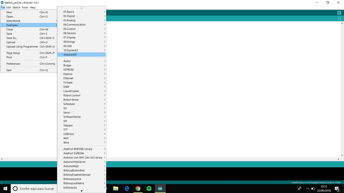
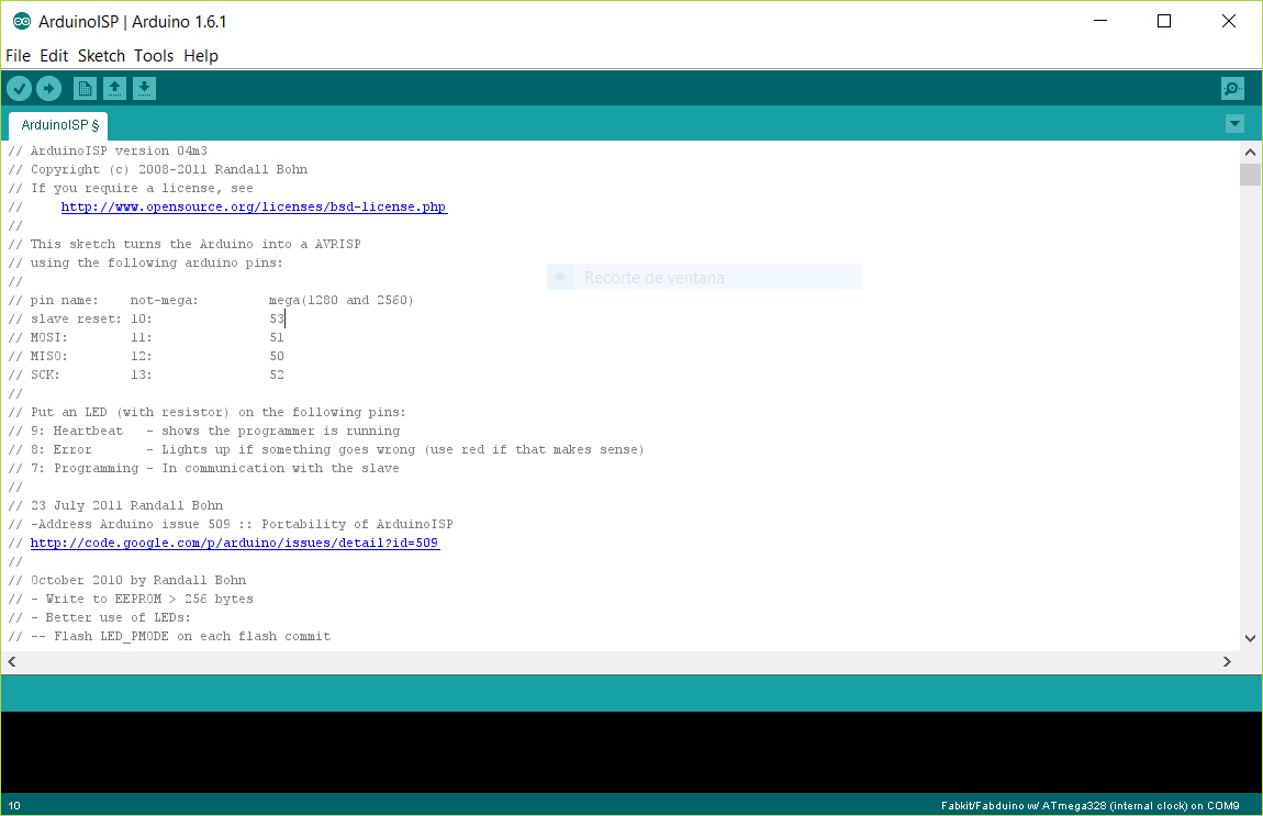
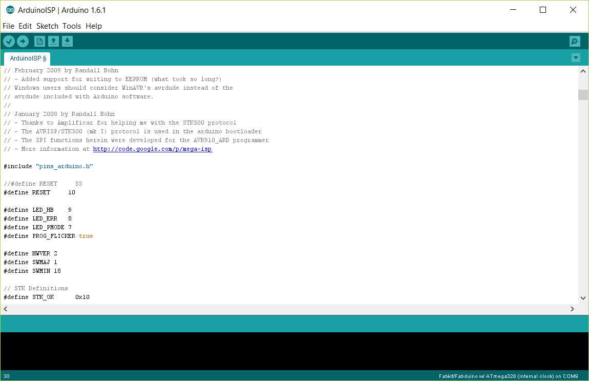
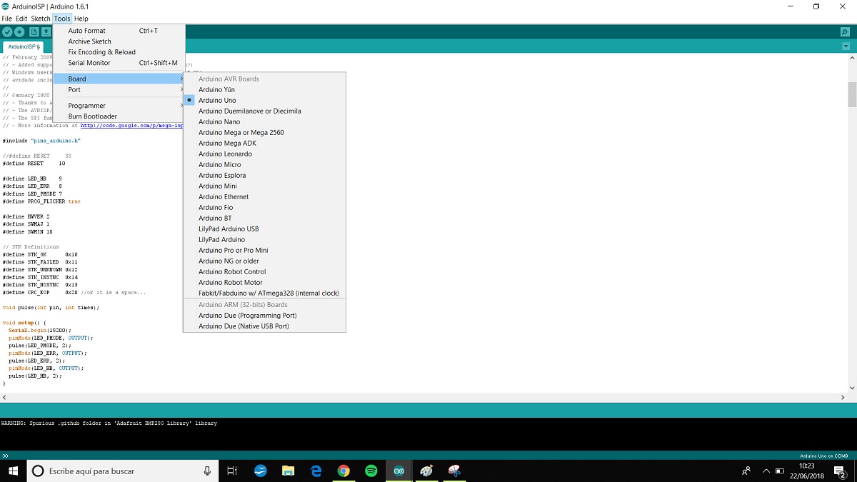
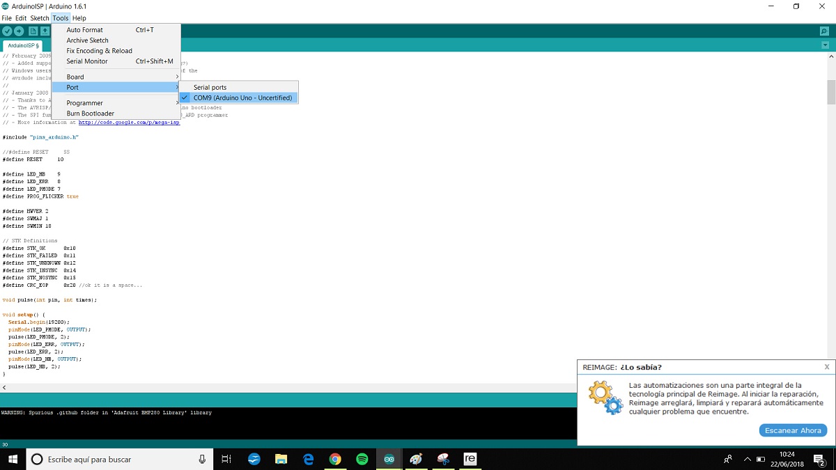
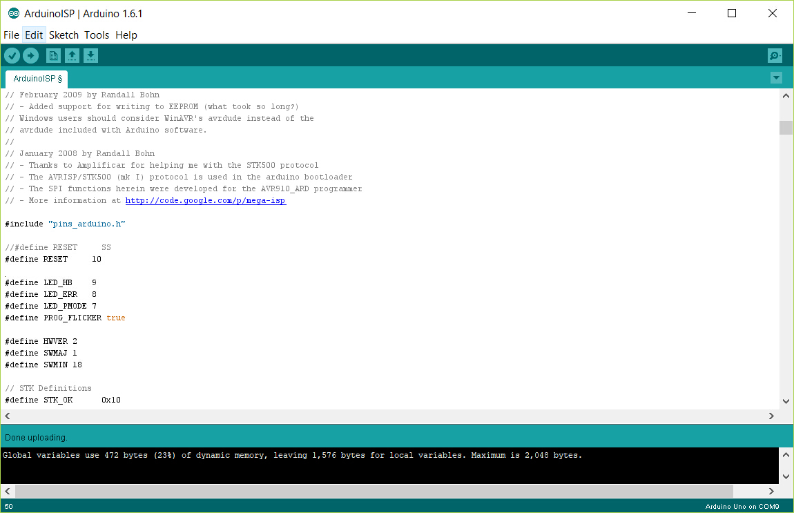
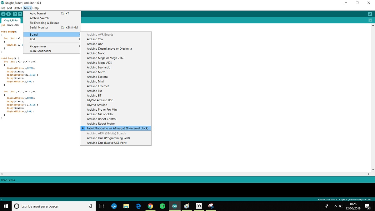
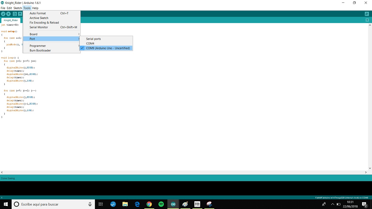
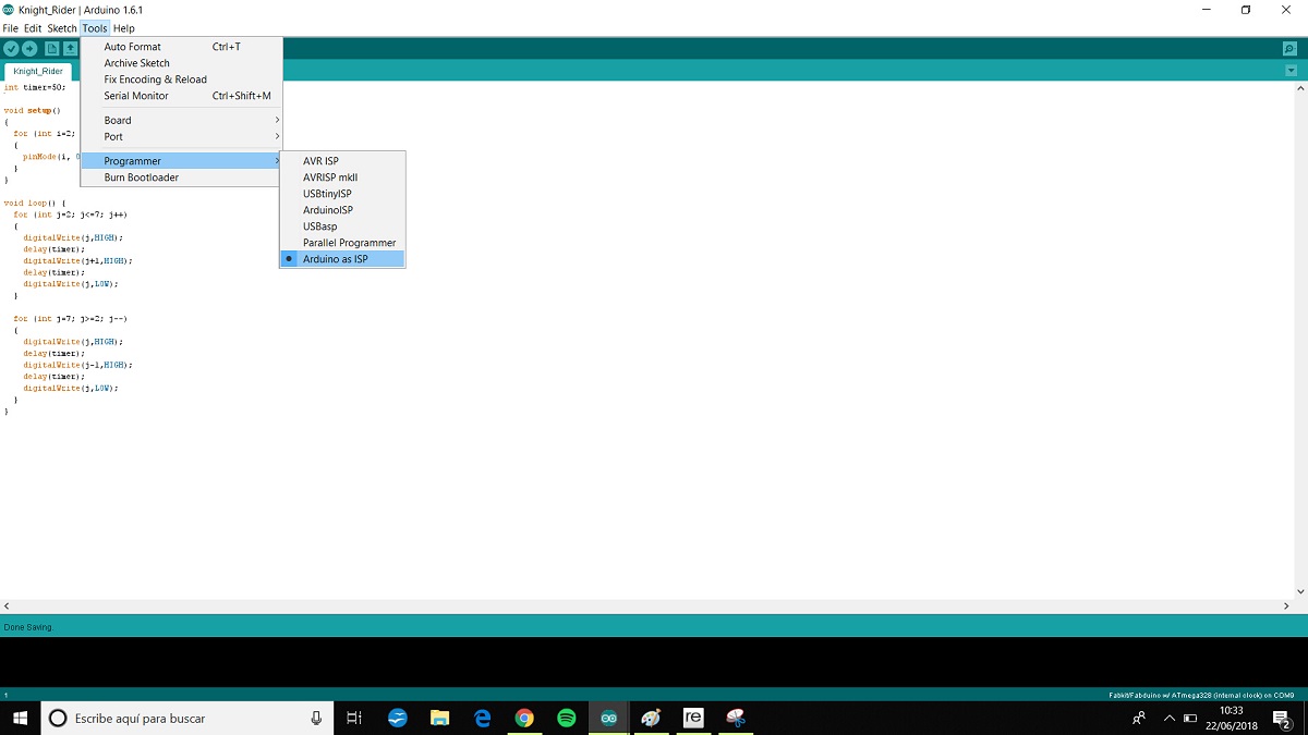
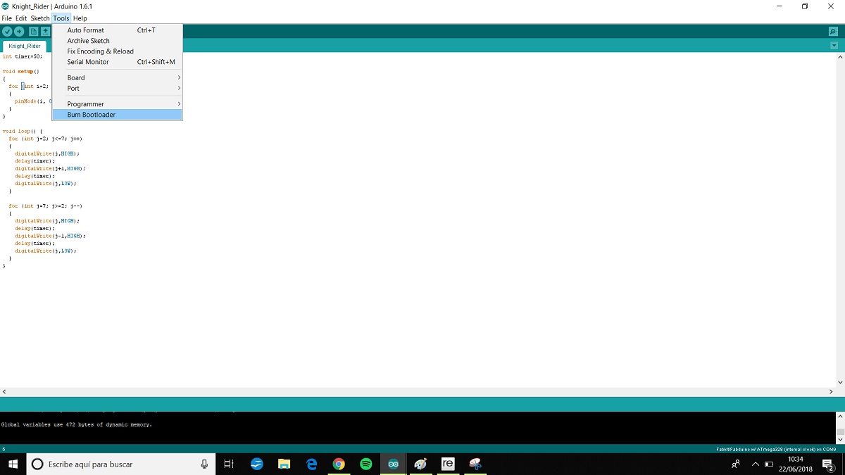
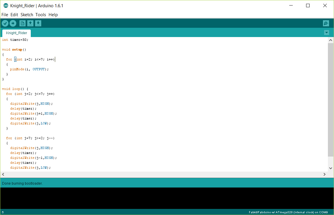
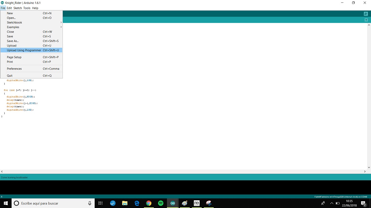
Using Arduino
I made a Fabduino board for the input assignment and i want to try the knight rider program