Week 3 - Computer-controlled cutting
Assignment
Make lasercutter test part(s), varying cutting settings and slot dimensions
Cut something on the vinylcutter
Design, make, and document a parametric press-fit construction kit,accounting for the lasercutter kerf, which can be assembled in multiple ways
Laser Cutting
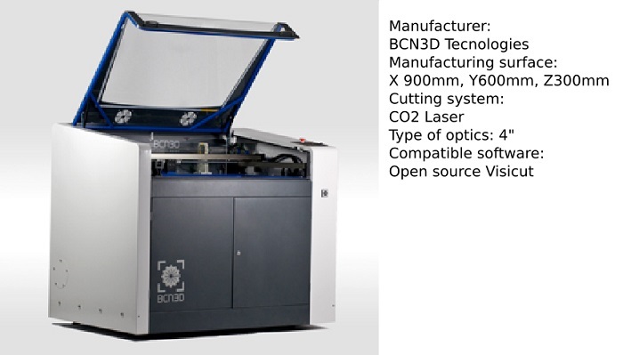
For exercise of the third week I used the laser cutter IGNIS that I have in my Lab. This laser cutter is a mid-range machine with a good quality / price ratio. This machine came to the workshop four weeks ago and we are still settingup the different configurations for different materials.
Designing and testing a Laser cutting workshop
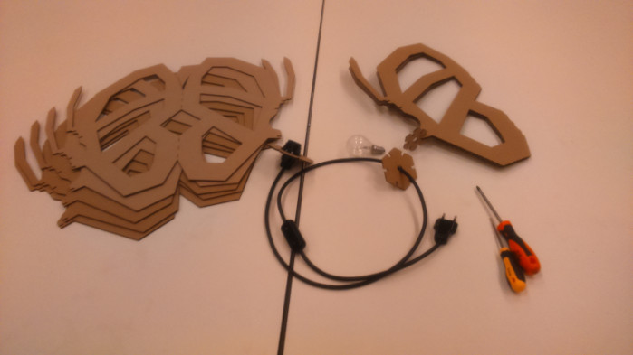
For the Computer-controlled cutting exercise I have designed a workshop to be done in four hours. The central idea is that participants design a lamp using inkscape as a drawing tool, and then cut it with the laser cutter and finally assemble the different parts. For this exercise I used recycled cardboard, cable xx mm, a switch, a socket and a 40W bulb. Material cost is 10 euros.
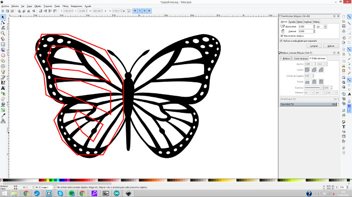
I copied a picture from the internet to use it as a guide for drawing (the theme could be anyone) I have the option to vectorize the image but I prefer to redraw to go faster also to show to the participant they can make their own version of an existing drawing.
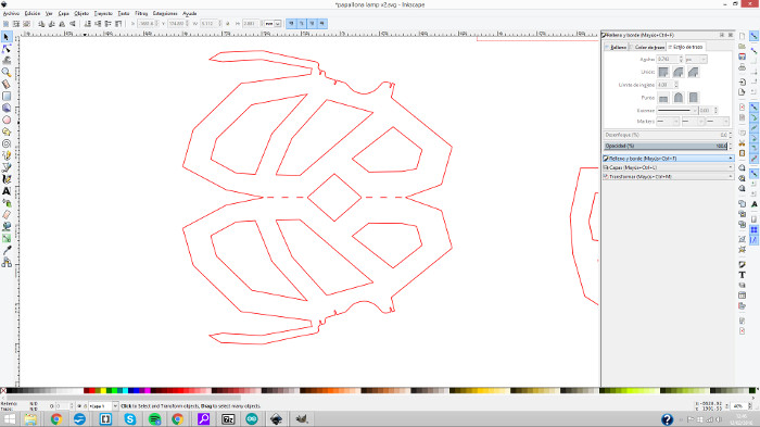
I've done the drawing with the Bezier curves and straigh lines tool choosing de secuence of straight lines segments mode , this part was easy. Then I marked the contour of the bulb, here I use the same tool and then edit nodes, adding, subtracting and editing curves. Finally joined the two drawings to make them one. For the workshop will be better if the participants starts the drawing with the bulb contour already made.
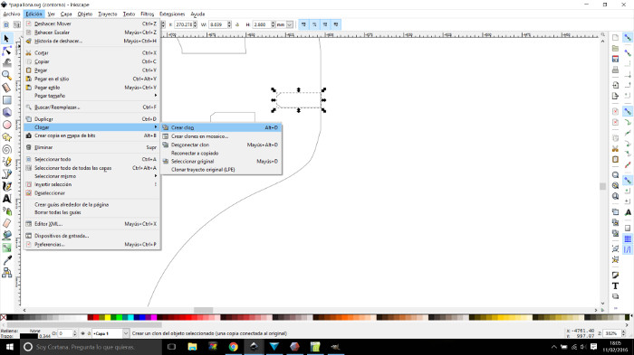
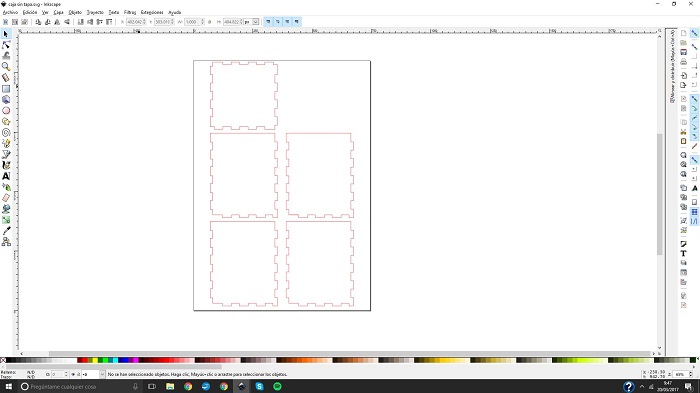
I draw what will be the slot for the fitting of the different pieces. The size of this slot depends on the results of the tests with the laser cutter. I cloned this item to modify it later.
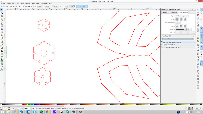
Continuing with the aesthetics of straight lines I've drawn some hexagons to design the joints between the wings of the butterfly. I will make the slot after the tests with the laser cutter machine, so here a made clons too to modify them later.
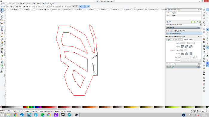
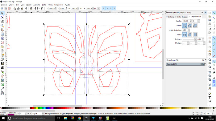
This is the final result, and ready to set to the thickness of the material
Using the Laser cutting Machine
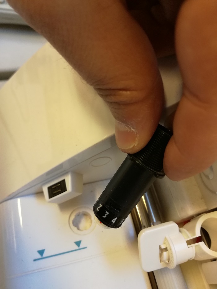
I use Visicut to send works to the laser cutting machine. It's easy and also simple. You can set differente profiles for different materials and then load it for a job. this software admits dxf and svg files.
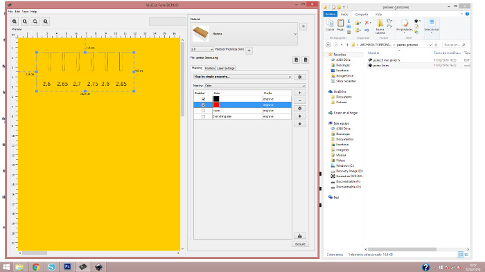
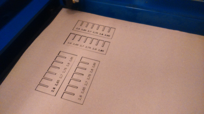
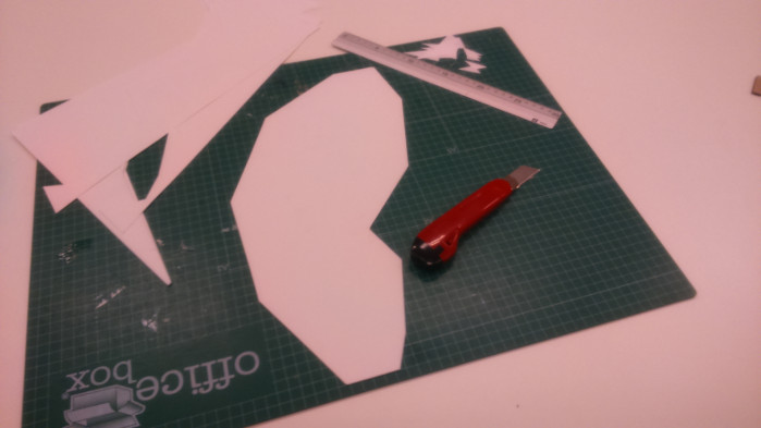
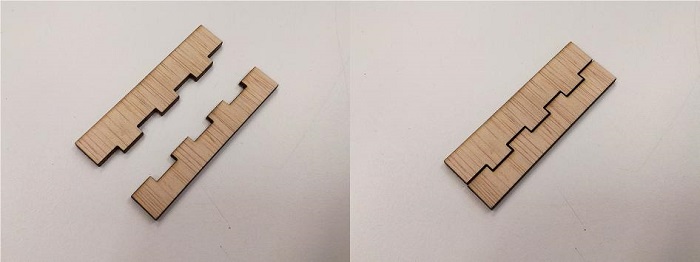
I used the drawing we made in class for the fitting test modifying the different parameters of the machine. The first goal was to find the correct power and speed for the chosen material.
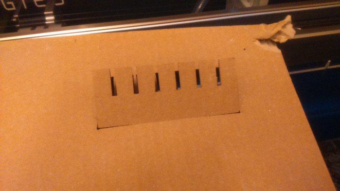
Once I found the correct settings for cutting i made a final cut whith the fitting piece to select the best fitting setup.
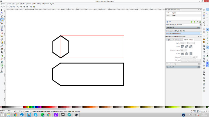
I cut both ways to see the difference. Cut the cardboard nerve perpendicular to the insertion is better
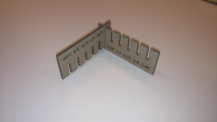
2,6 milimeters is the number! Back to the design drawing!
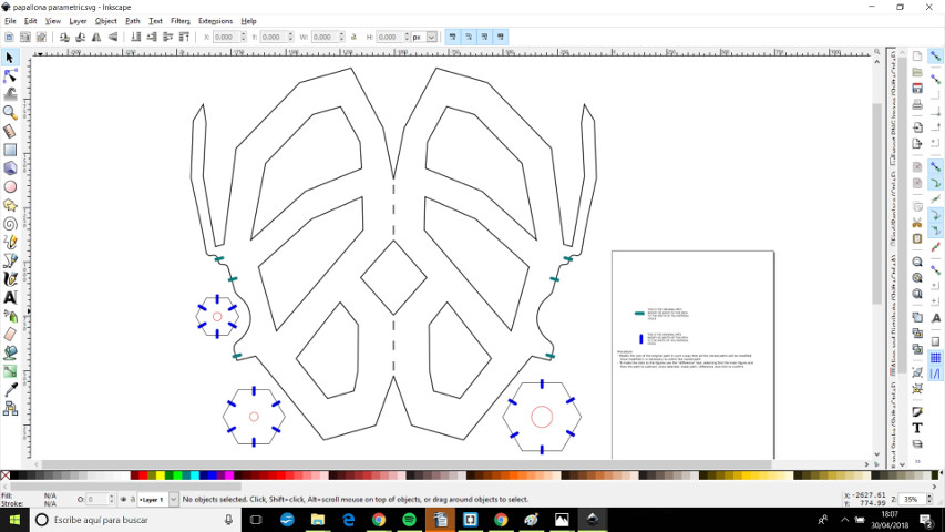
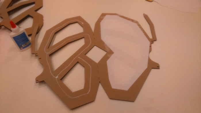
After adjusting the size of the fitting slots I have realized that the lamp is too big. Initially the lamp should be a table lamp, now it will be a ceiling lamp! To do this I had to change the orientation of the profile of the bulb. Another important change is that I decided to make each wing with double leaf to put a diffuser inside. This change also makes me enlarge the fitting slot of pieces that connect the wings of the butterfly.
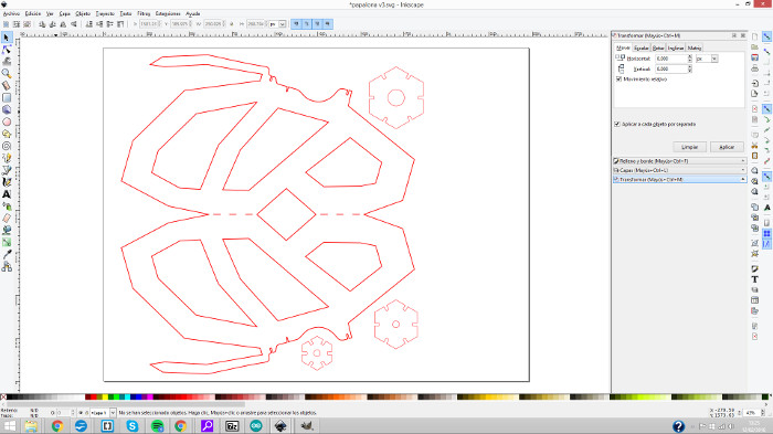
This is the final file for the lasser cutting machine
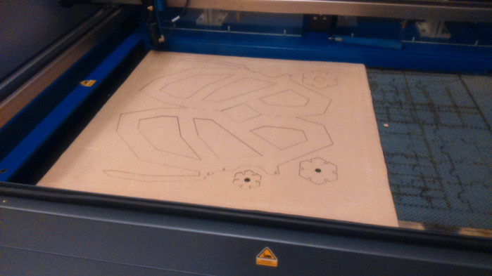
First cut
Almost ready for the assembly work
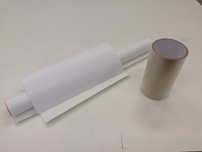
I used paper for the diffusers
A little bit of glue for the paper and Ready for assembly, I hope that the material resist the folded and helps to a better fit
Ready for assembly, I hope that the material restance to folded helps to a better fit
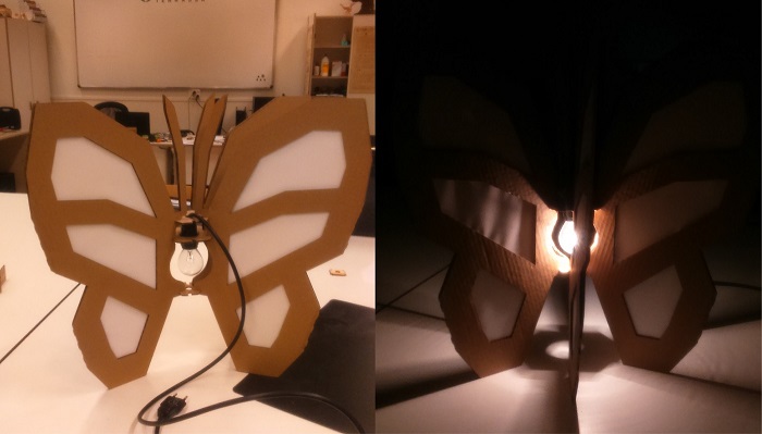
finishing assembling and testing the light
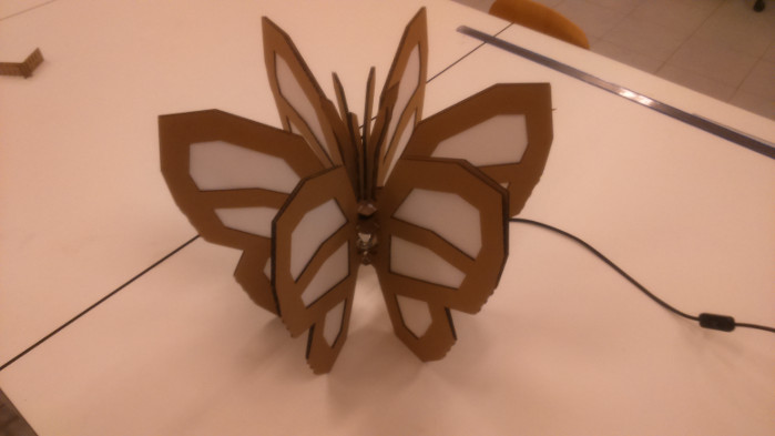
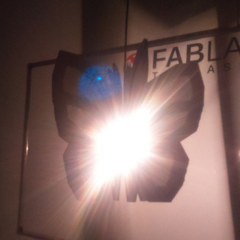
The lamp is ready to be hang!
next time I'll have to use a thinner electric cable!
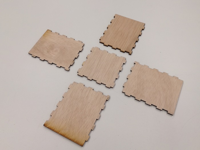
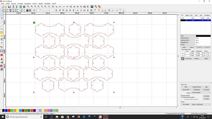
Another exercise! I'm going to make a box with press fit unions. I have done a design but before I do some tests and see if the parts fits correctly.
This is a simple but interesting design to work with children who are learning to design in 2d, they can make designs to apply to the faces of the box, cutting, recording or marking.
After several tests with decimals of millimeters of difference I have found the correct measurement. This fit will not be the same for all laser cutting machines, each machine cuts differently.
it looks good!
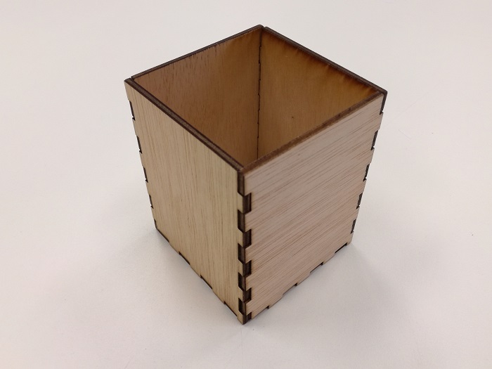
If we flip the pieces the fit will be different
Vinyl Cutting
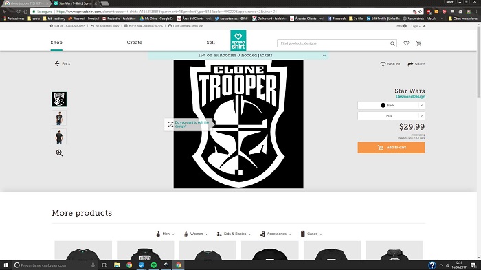
Searching an image from internet. Copy image
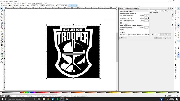
Paste image in Inkscape
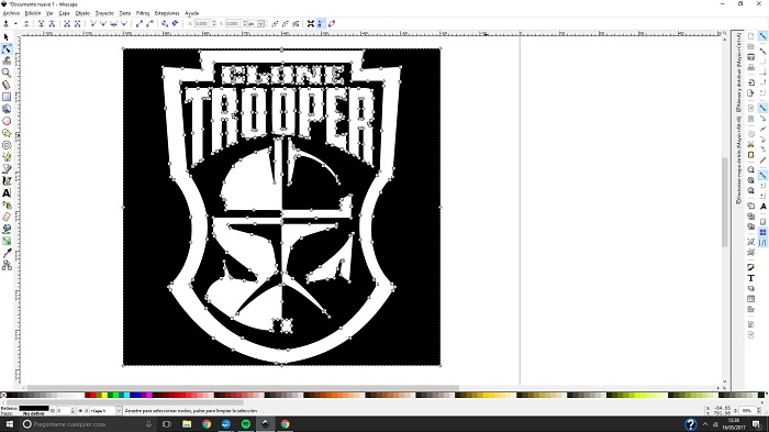
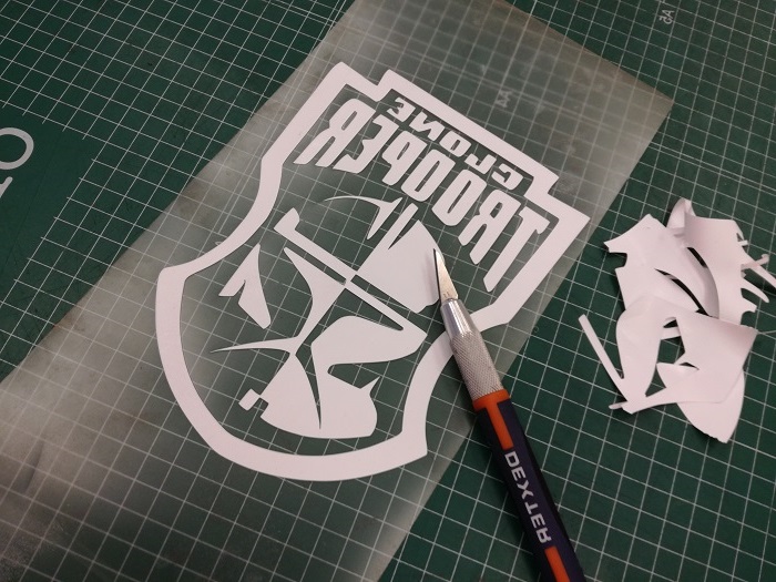
Vectorize the image for editing.
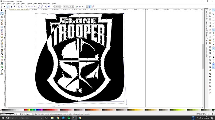
I don't want the black background.
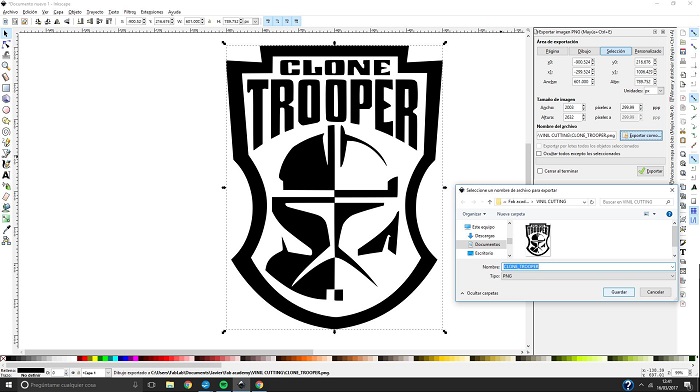
Edition final result, ready to export as image
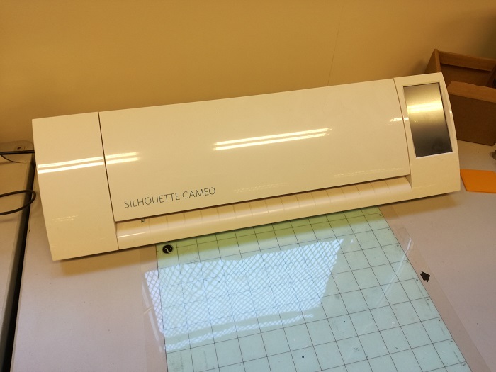
I'm going to use ther Silhoutte for the vinil cutting
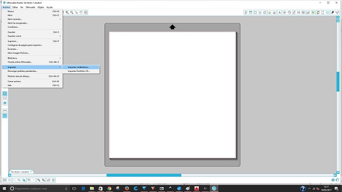
Silhoutte has it's own software and it's very easy to use
First we have to add the image to the silhoutte library and the make double clik to insert the image in the work space.
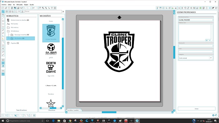
We can modify the size of the image draging from one of the image corner
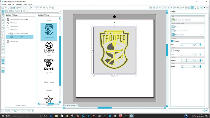
Next step is to "Trace" the image by selecting the trace tool button, we must define a "Trace Area" and then set the different filters until the image turns tottaly yellow, then click on the "Trace" button
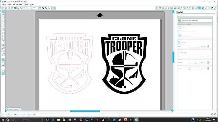
Image is already traced and we have the image and the trace result in the work area. Errase the image and keep the trace result
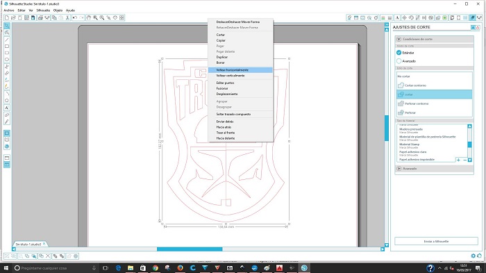
I'm goin to use heat press vinyl to make a t-shirt. in this case is necessary to flip the image. Selecting the trace click right button an then "Flip horizontally".
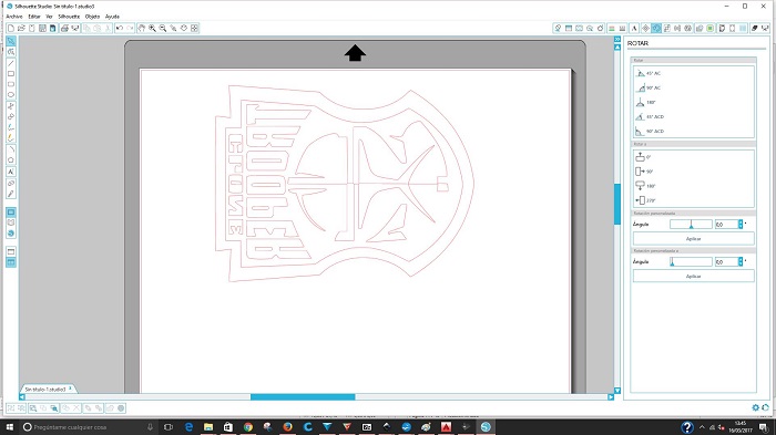
I will rotate it to make a better use of the material.
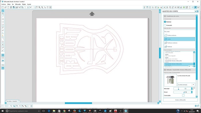
It`s time to Cut, Select the tool for cutting on superior righ corner to set the material we are going to use. When you set the material the softwares indicate us the position of the cutting blade. The position indicates how deep it cuts depending on the material thickness
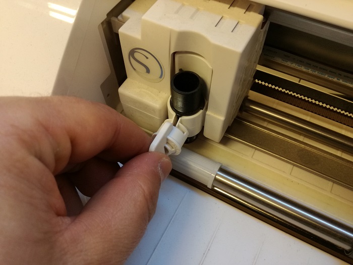
Remove the blade
Set the blade position and inser it.
Here the vinyl and transfer that in this case we don't need to use because the heat press vinyl material has it's own transfer.
Load the material and "Send to silhoutte" to star cutting
Remove the vinyl that is no parrt of the design
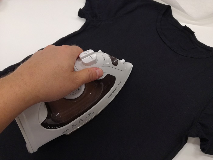
Iron the T-Shirt before to get a flat suface
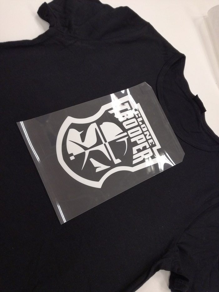
Place the vinyl
Use waxed paper, the same we uso in the kitchen oven
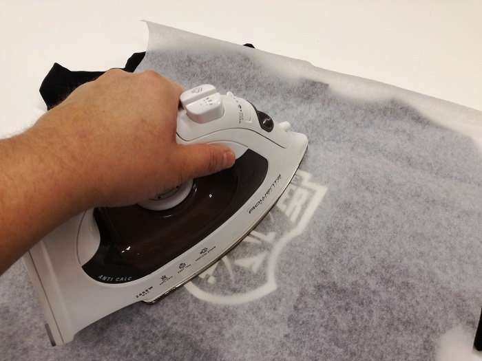
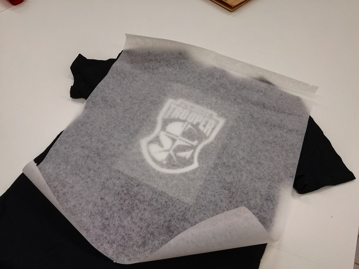
Press during the iron until the transfer starts to wrinkle
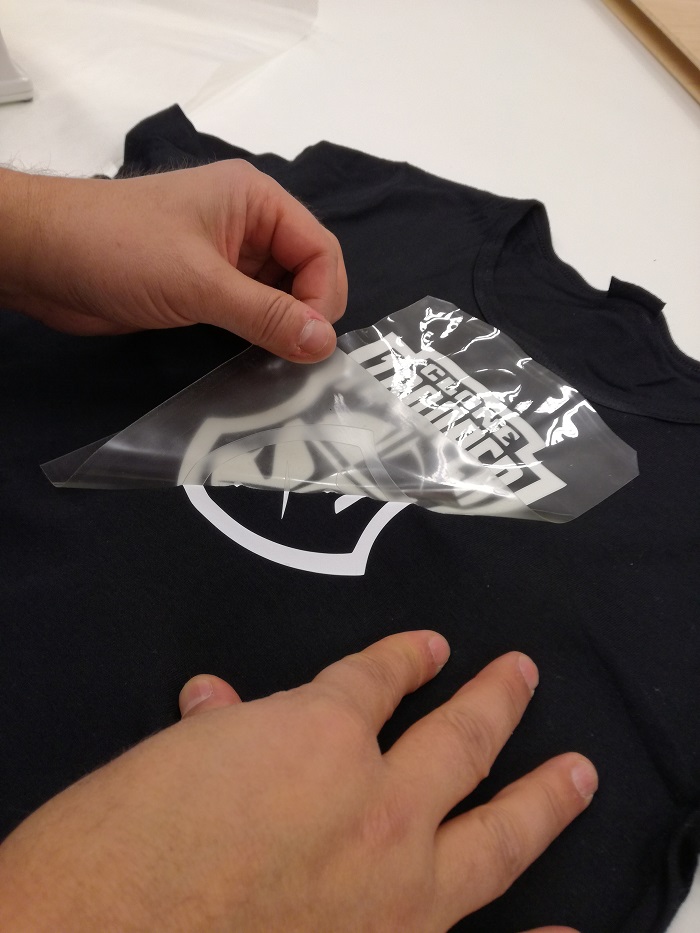
Remove the transfer carefully
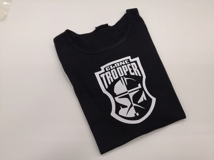
Final resul
Parametric press-fit construction kit
This assignment should be a group work but as I mentioned before I regento a fablab and besides the lack of time I know that in my laboratory I can do things more quickly
Drawing with solid works
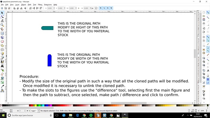
I want to make a drawing in which I can modify certain dimensions according to the material that I will use to cut with the laser cutting machine.
Open the Solid Works 2017. This program allows the design and modeling of parts and assemblies in 3D. It is a program with intuitive and detailed operations step by step. On the left is the operations tree where we can modify any operation carried out along the modeling.
The main operations are located in the top bar. Click on the sketch generation.
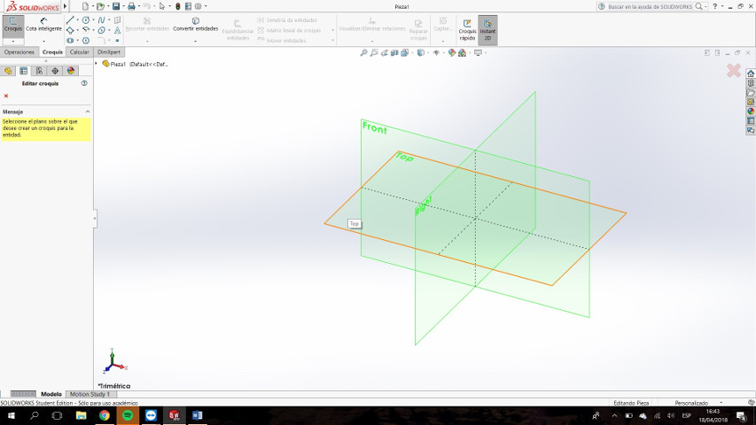
Choose the plane where we want to draw our sketch. This implies the position of the piece in space.
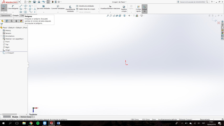
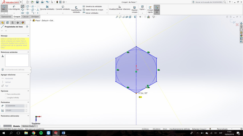
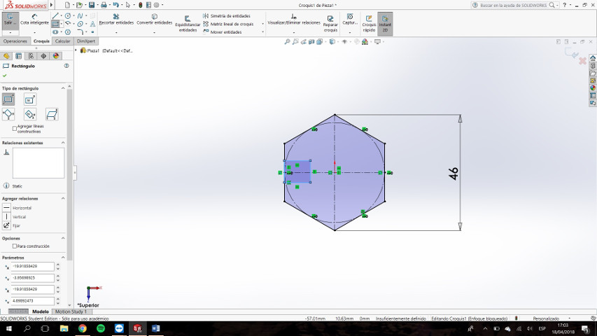
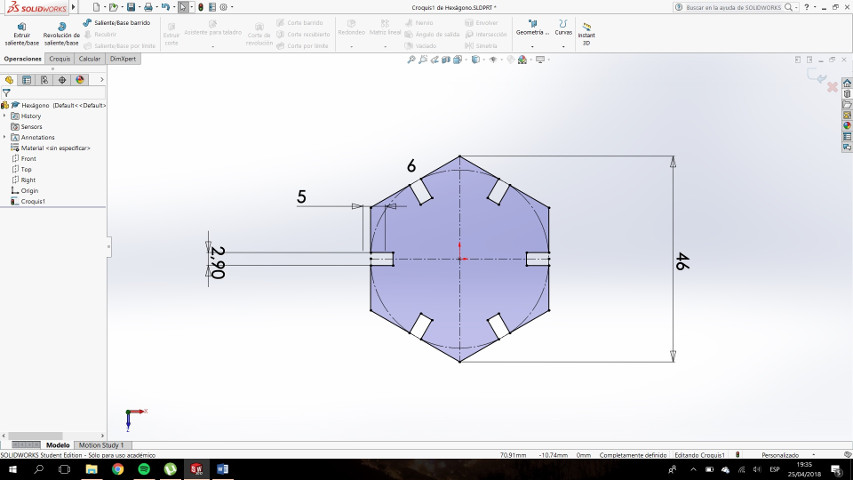
Within the sketch operation, our table of operations changes to the table of sketch sketch tools. Here we will find all the tools to be able to draw the sketches in 2D. Click on the hexagon tool.
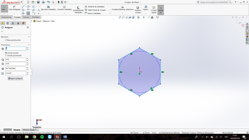
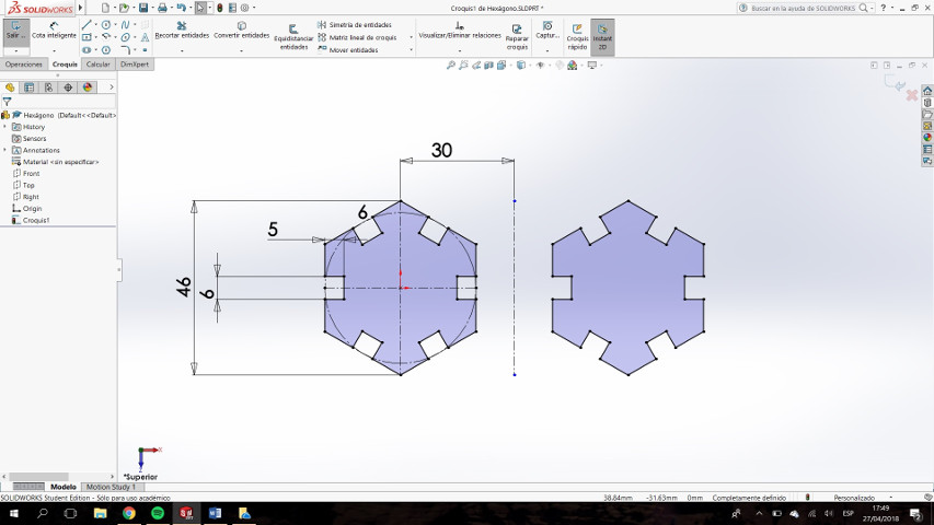
Click on the coordinate center. Now we draw the hexagon. The size is indifferent. Later we will determine it.
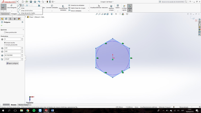
Click the construction line tool.
Draw a vertical line. From end to end.
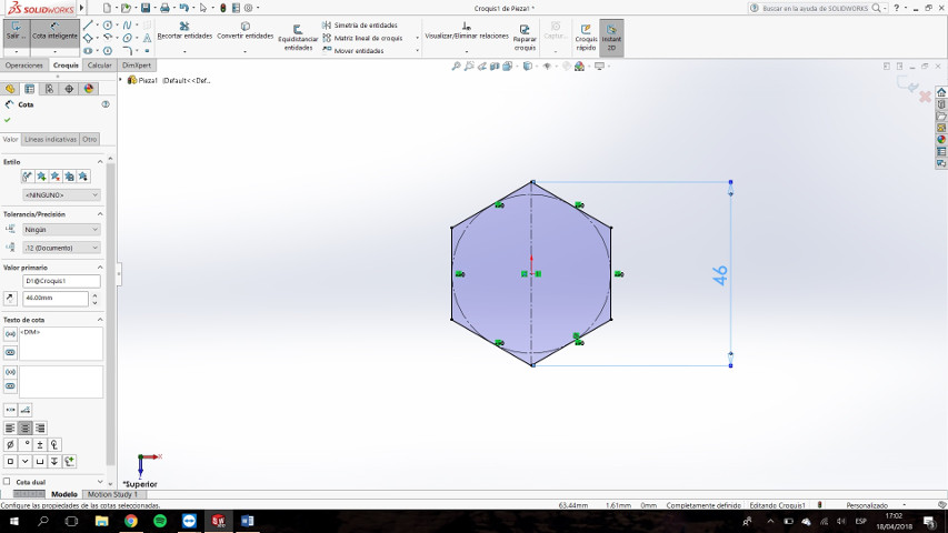
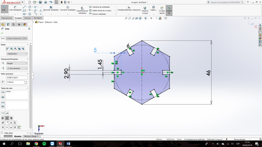
With the intelligent dimension tool, delimit the distance between opposite vertices of the hexagon.
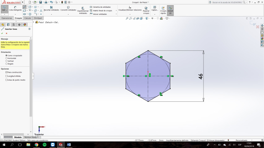
Draw another construction line, this time horizontal.
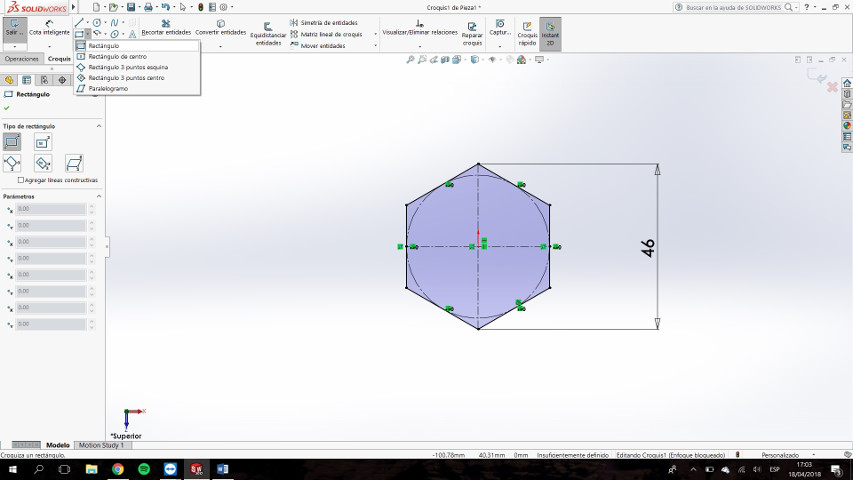
Click on the rectangle generation tool. If we click on the arrow, all the rectangle variables we can do will be displayed.
Draw a rectangle on one of the faces. This rectangle will be our future notch.

Set the dimensions of the rectangle.
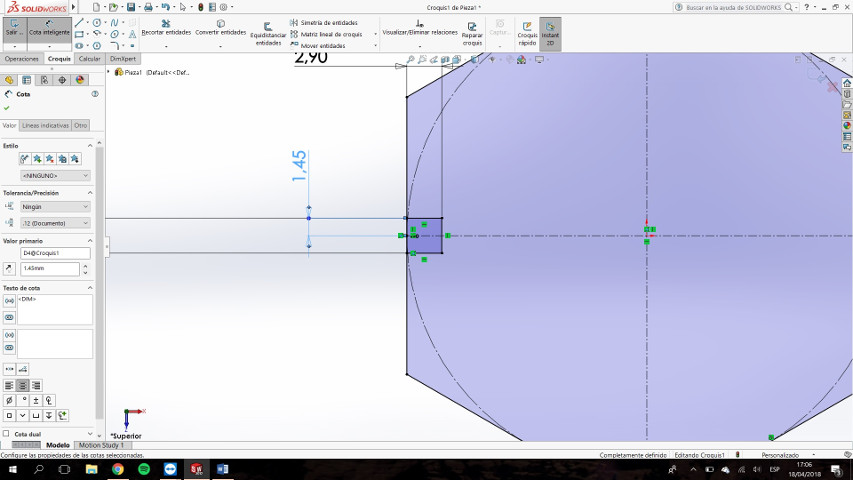
Set the distance to the horizontal construction line. In this way we center the rectangle.
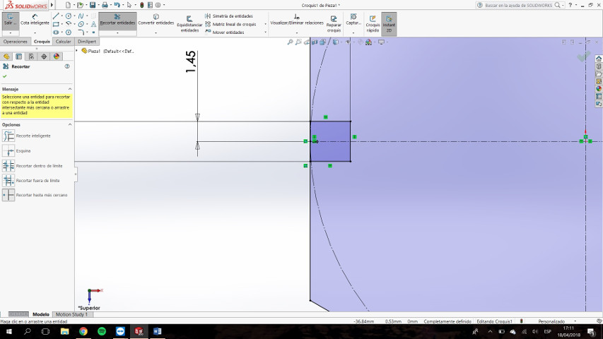
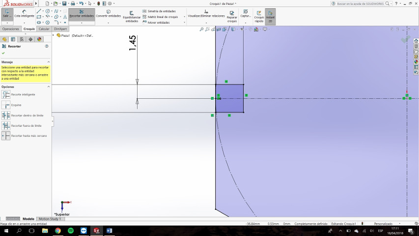
Select the tool to trim entities. In the sub-options we choose "Trim to nearest". We cut all the lines that are on the left side of the rectangle.
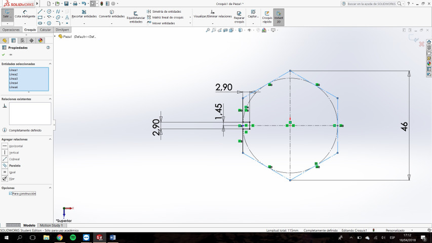
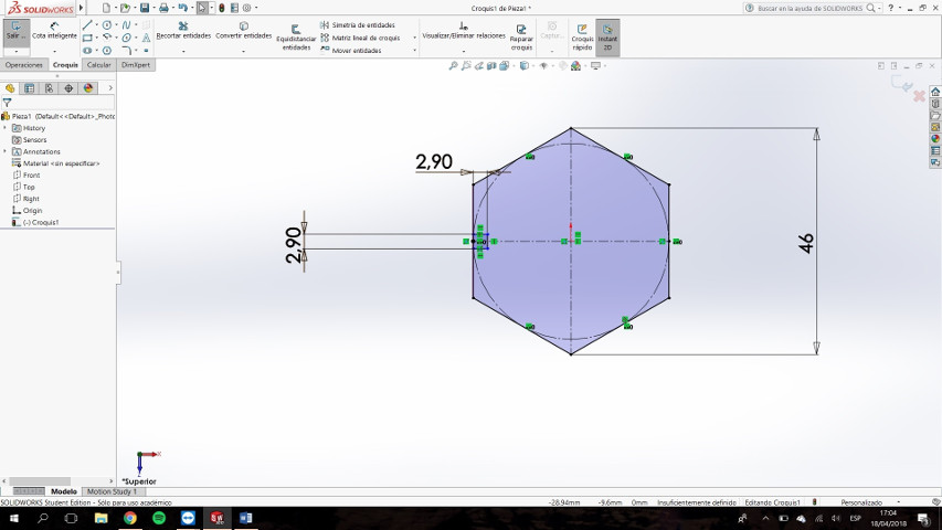
Select all the faces that are not in contact with the rectangle and in the sub-option we give "for construction".
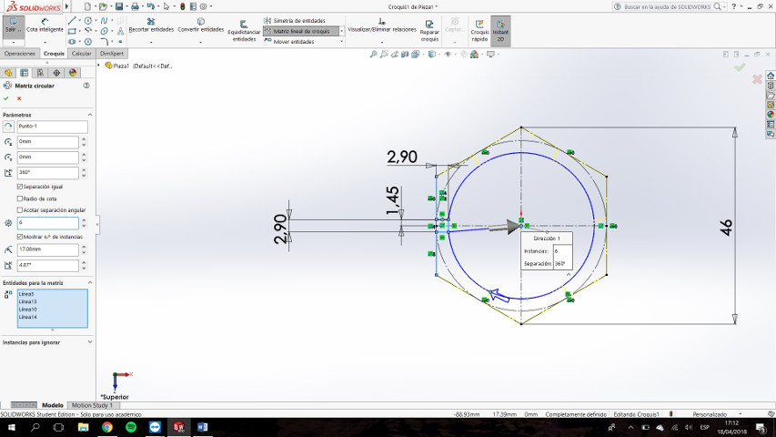
Within the Linear Sketch Matrix tool, we select circular matrix. We select the continuous lines and apply the mentioned parameters.
The hexagon should look like this.
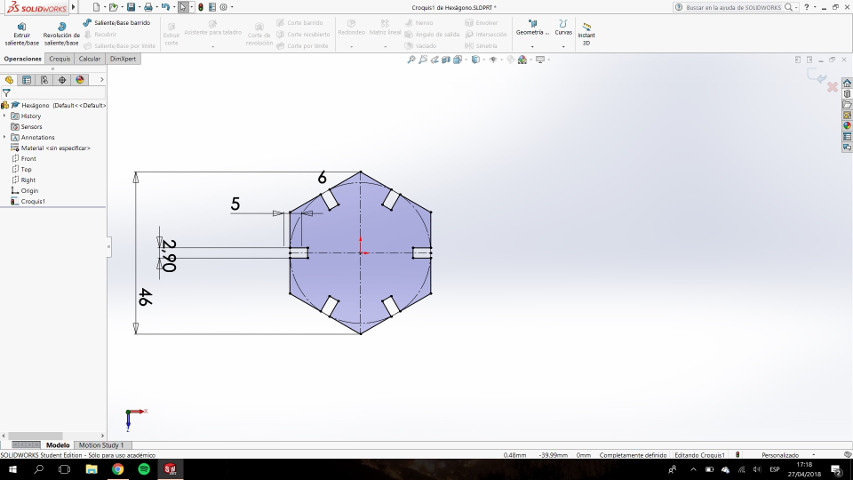
We modify the depth of the notch, the rest of the notches should be modified equally.
Delete the dimension that centers the notch with the horizontal line and select the midpoint of the vertical line and the horizontal construction line. In the sub-option set "Coincident".

From now on, any dimension that is modified drags the change to the rest of the hexagon. This is called parametric design.
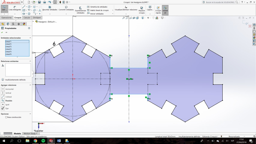
We will draw another object from the one we have already created
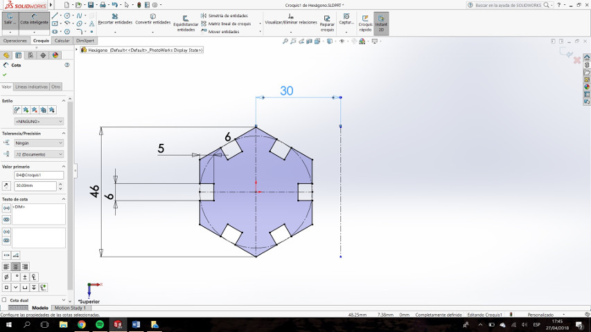
From the hexagon we made, we will make the necessary modifications to make the double hexagon. It is recommended to save as a new file.
Draw a line for vertical construction and delimit it 30mm from the center of the hexagon.
Select the perimeter lines of the hexagon and use the operation of symmetry with respect to the line that we have just drawn.
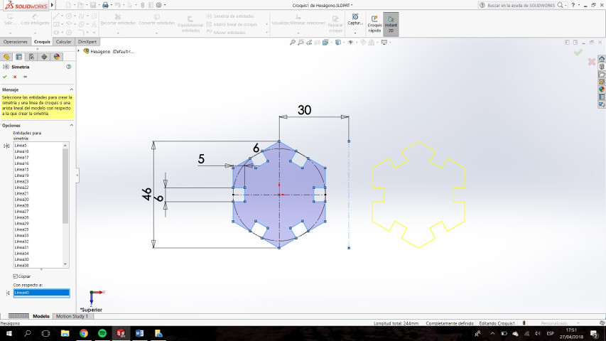
This is how it looks
Select the lines that form the facing faces and make them for construction
Join both the top and bottom of the two hexagons.
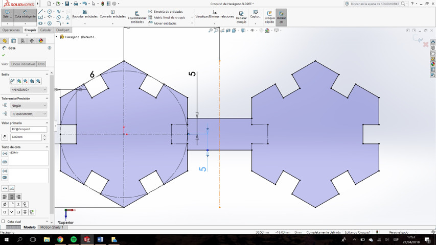
Set the distance to both unions.
this is all!.
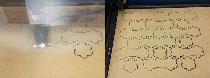
Cutting whit laser cutting machine
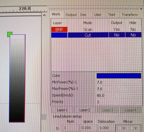
We have changed the software that manages the laser cutter, although for the first part of the assignment I use "visicut", now I will use RD Works.
This software allows you to make simple drawings, which was not possible with the previous one. We can also control the machine from the computer. Is better!
In this software we can only play with power and speed, no frecuency values to modify. The same happens whit Visicut.
There is an important factor when we are going to laser cut. The distance from the laser exit point to the material to be cut
The type of lens will make the distance different
When the laser passes through the lens it comes out conically to coincide at a point. That point should be the center of the material but nowadays people usually use the surface of the material as a reference since in this way the thickness of the cut can be seen. The result of the anteria is a song with a slight angle of inclination almost imperceptible
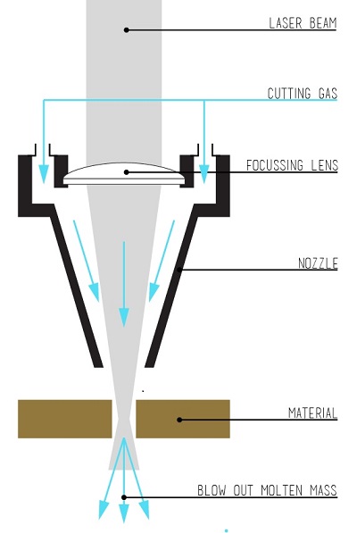
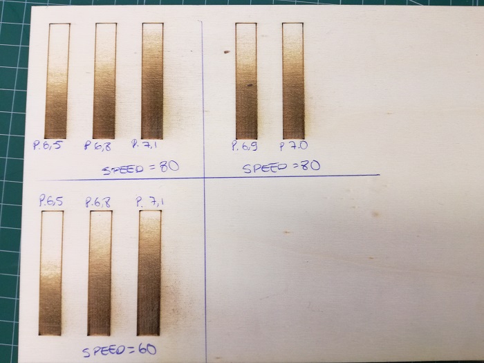
If this distance of which we have spoken is not correct, the result of the cut is very bad. For that, tests are made adapting the distance, raising or lowering the cutting bed.
Different material, different values, different thickness, different values.
Besides Cutting there are other processes like Marking and engraving.
Mark is like drawing, not cutting, with the power enough to burn the material and the speed enough to not cut the material
Engrave is the drawing but filled. It takes a long time.
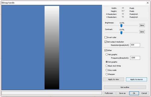
I made an engraving test using an image. RD Works software has a window to setup the image output.
It works with resolution (dpi) and a Net graphic Frequence. It's a matter of try and see what happens
You can see that there's a minimum and maximun power, the soft allows to set that values but my machine cant.
Once the resolution is set, we have to try differents 'Power' values and differents 'Speed' values.
The thing is which one you like most for the work your are going to make.
After several tests ( a continuos work in the Lab) with the machine we have the different values to apply depending on the material, the thickness of the material and the process to be done
For this work I set the minimum and maximum power at 40 and the speed at 20, I'm cutting DM and these values are what we have right now.
Looks nice!
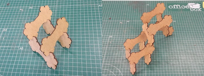
First parametric construction
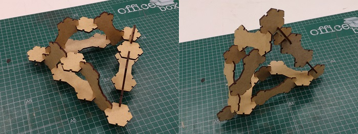
Second parametric construction
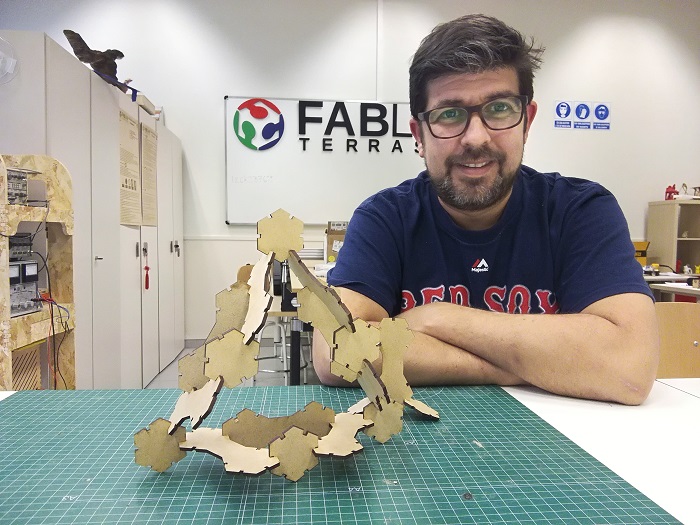
Happy end!
Conclusions:
While we can have a table with pre-established values (materials, thicknesses and processes), these values can only serve as a guide to perform new tests, whenever we are going to perform a new job we must do these tests. The materials are not homogeneous, they are not the same, the lens can be more or less dirty, or the bed can be more or less level
These values can only be used if they have the same machine, calibrated in the same way and the laser in the same conditions of use. That is, they will only serve as a guide. These values vary and every time you are going to cut something with the laser cutting machine it is necessary to do some tests before a definitive cut.