week 14 & 15 - mechanical & machine design
group assignment week 14:
- design a machine that includes mechanism+actuation+automation
- build the mechanical parts and operate it manually
- document the group project and your individual contribution
group assignment week 15:
- actuate and automate your machine
- document the group project and your individual contribution
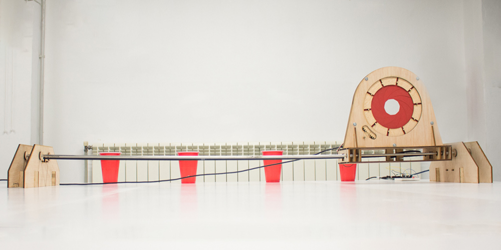
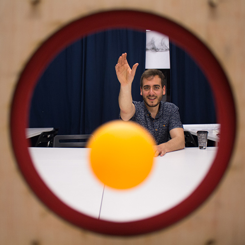
iris pong!
Group website

process
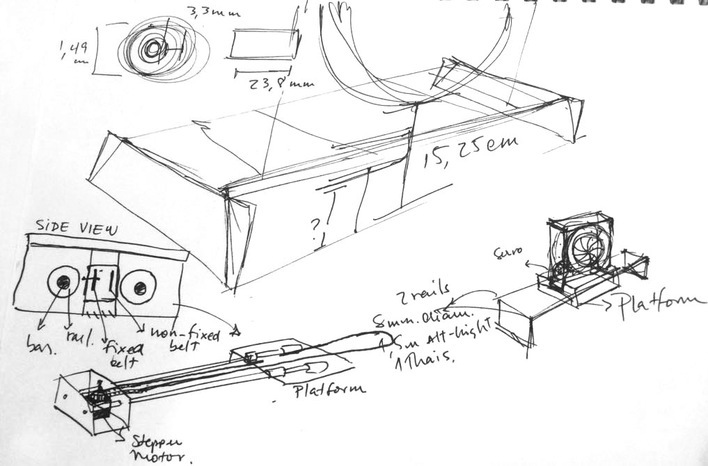
In this week assignment we have to design a machine. We decided to make an iris or diaphragm which will open and close while moving on a railing. This will be used as a pingpong/beerpong game.
Baptiste found a page that has an iris calculator. It’s an online software tool that helps design and make mechanical iris diaphragm apertures given a set of specifications. This is great because we don’t have to work from scratch and it basically means we have a parametric page to help out if we decide to change the specifications of our project down the line. The final design can be downloaded directly from the page as a .DXF file.
We’ve divided the tasks, more or less. Baptiste will be gone for the whole week so he’ll be working remotely on the group page for our project, Thais and I will be working on the mechanical design of the iris and Daniel is investigating on the mechanical design of the axis.
The final sets used for the iris are these:

The generator works out some dimensions quite well but doesn’t give you a fully done design. You might expect a fully solid 3D design, but it comes out as an exclusively 2D set of layered drawing that more or less constitute the parts of the iris. But for our purposes, that was enough.
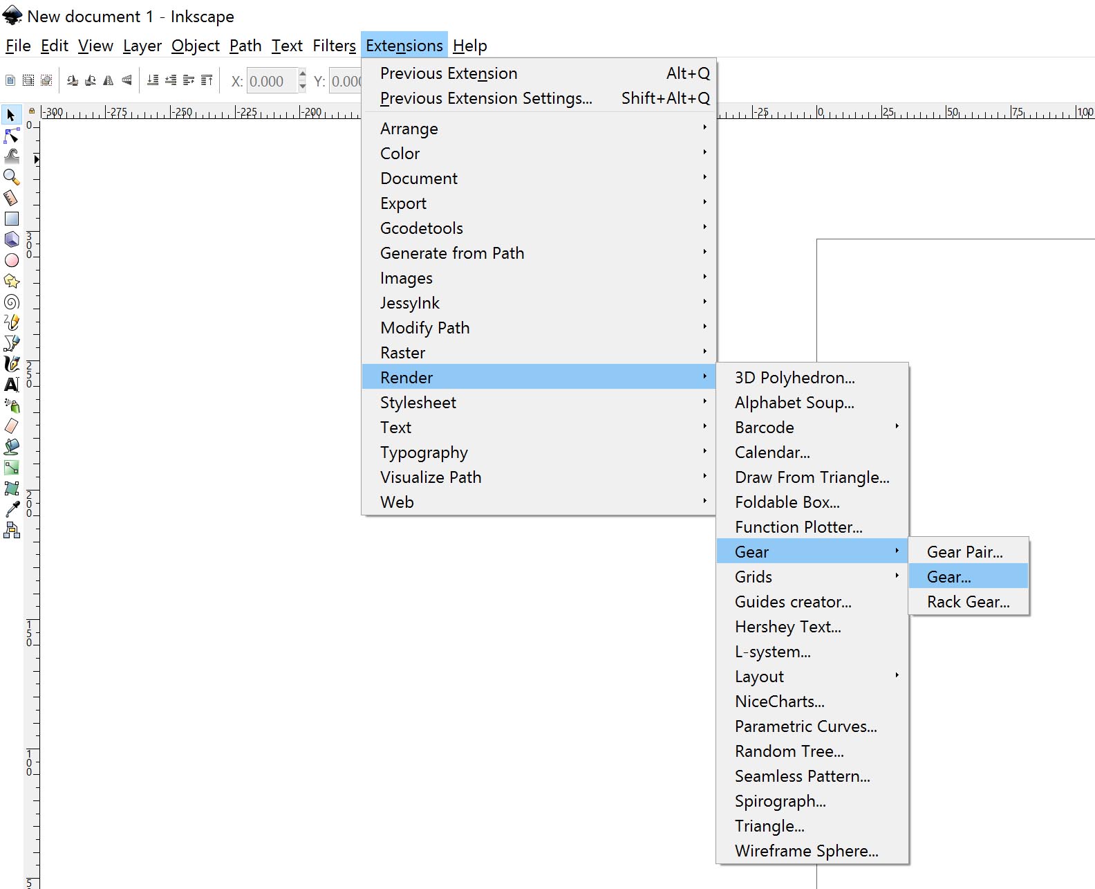
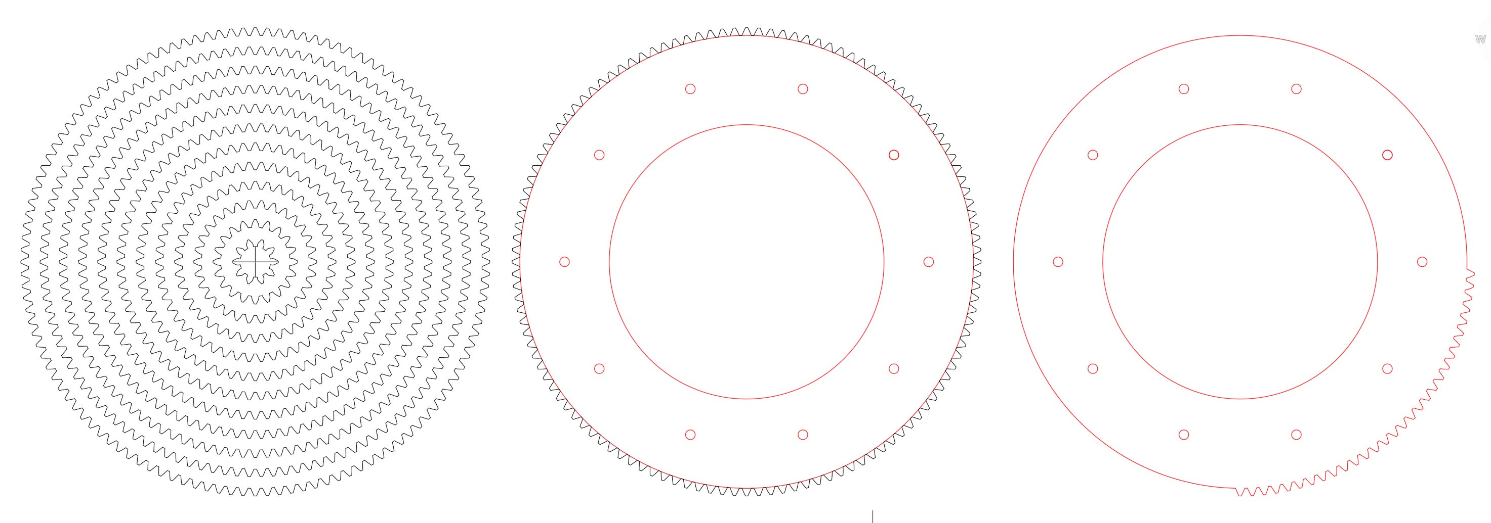
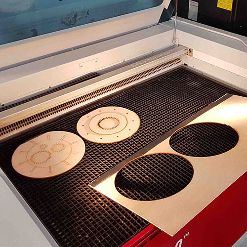
I added some gears to the iris mechanism. In inkscape there is an option to make your gears. You can't choose however the diameter of your gear. To make the gear bigger or smaller you can do it by choosing the number of teeth. We made several gears with the same size of teeth but different number (10,20,30,40,50 teeth....) so we can choose one gear for the iris ring and one gear for the servo motor.

We exported the file to dxf so we can work more confortable with Autocad. We chose the gear with 120 teeth for the iris ring. However the diameter was not exactly the one we wanted so we scaled all the gears so the 120-tooth gear matched the iris ring. Then we deleted all the tooth not necessary for the iris movement. That movement angle is the one told by the Iris Calculator.
For the servo motor we cut different size in order to choose the perfect size of gear to attach to the servo motor.
The blades were cut in paper in groups of two to fit the DINA4 color paper size.
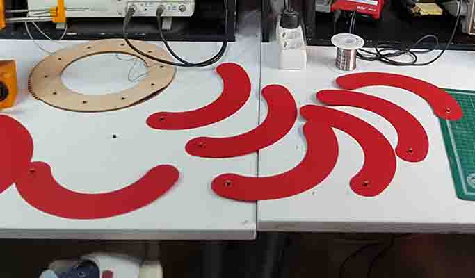
The result worked nicely. Now we have to design the whole machine.
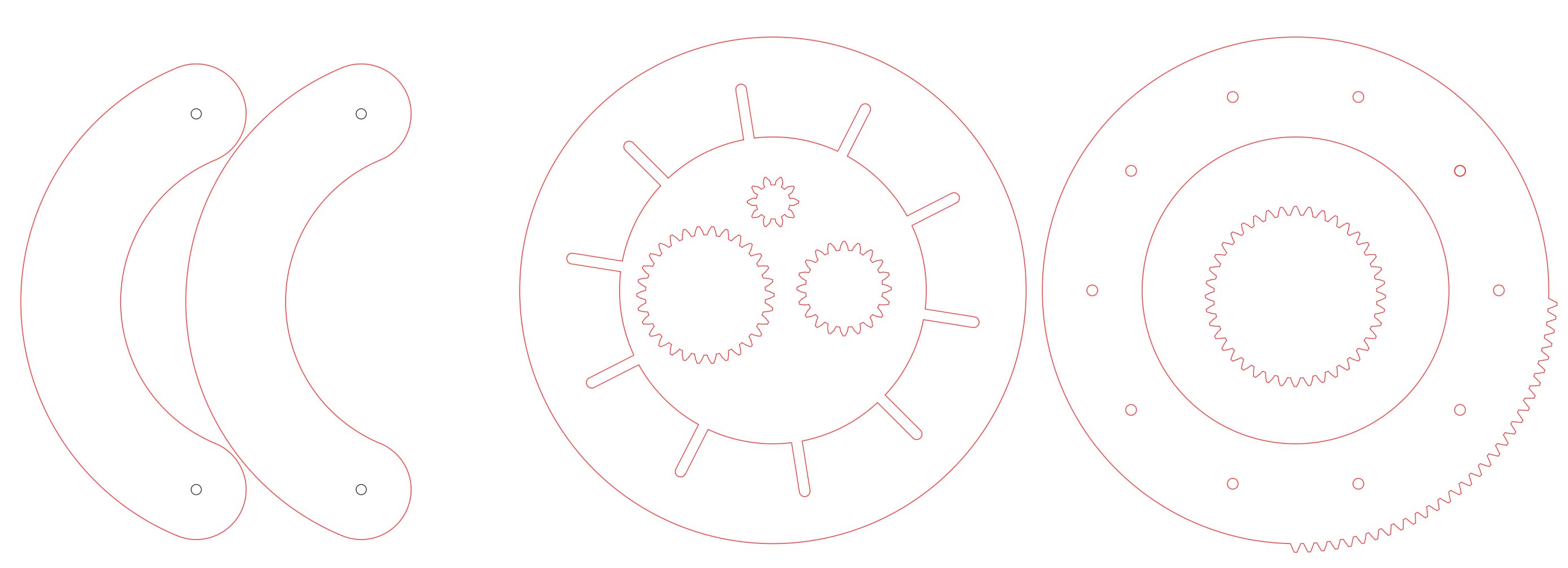
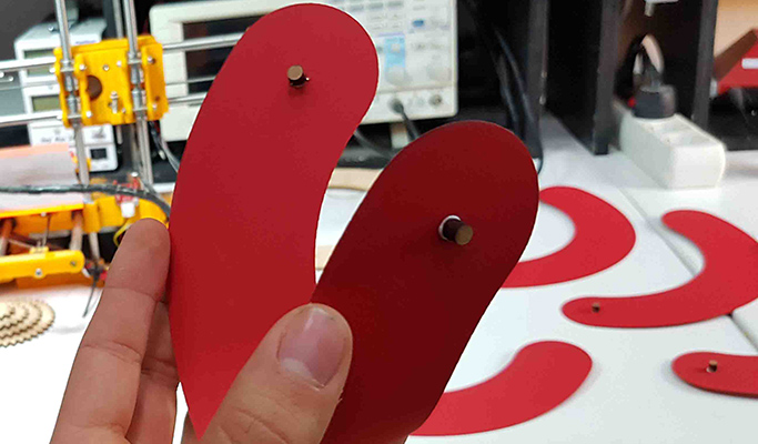
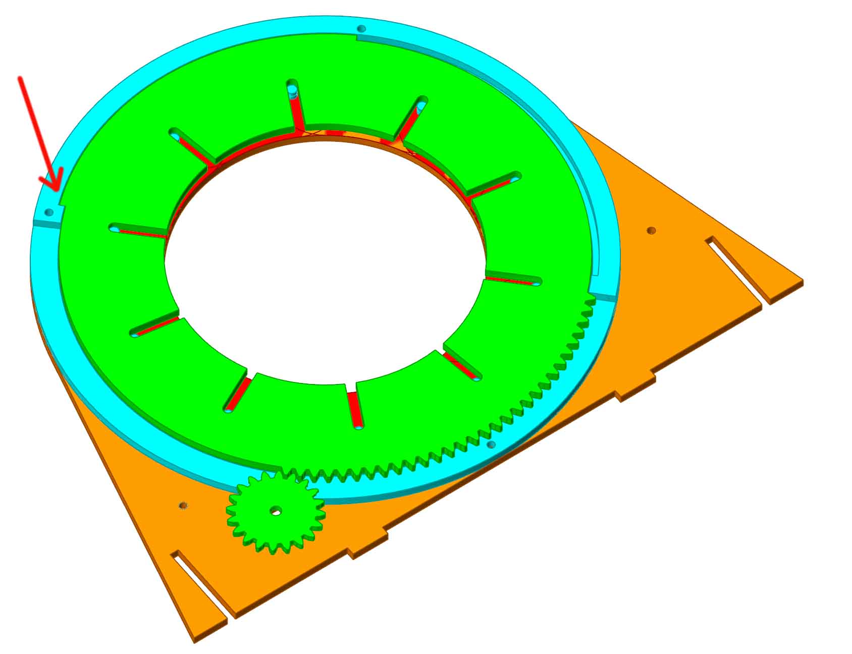
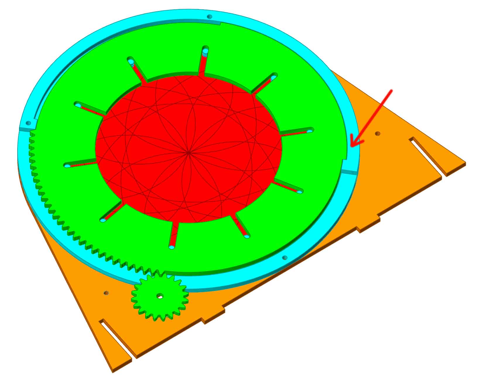
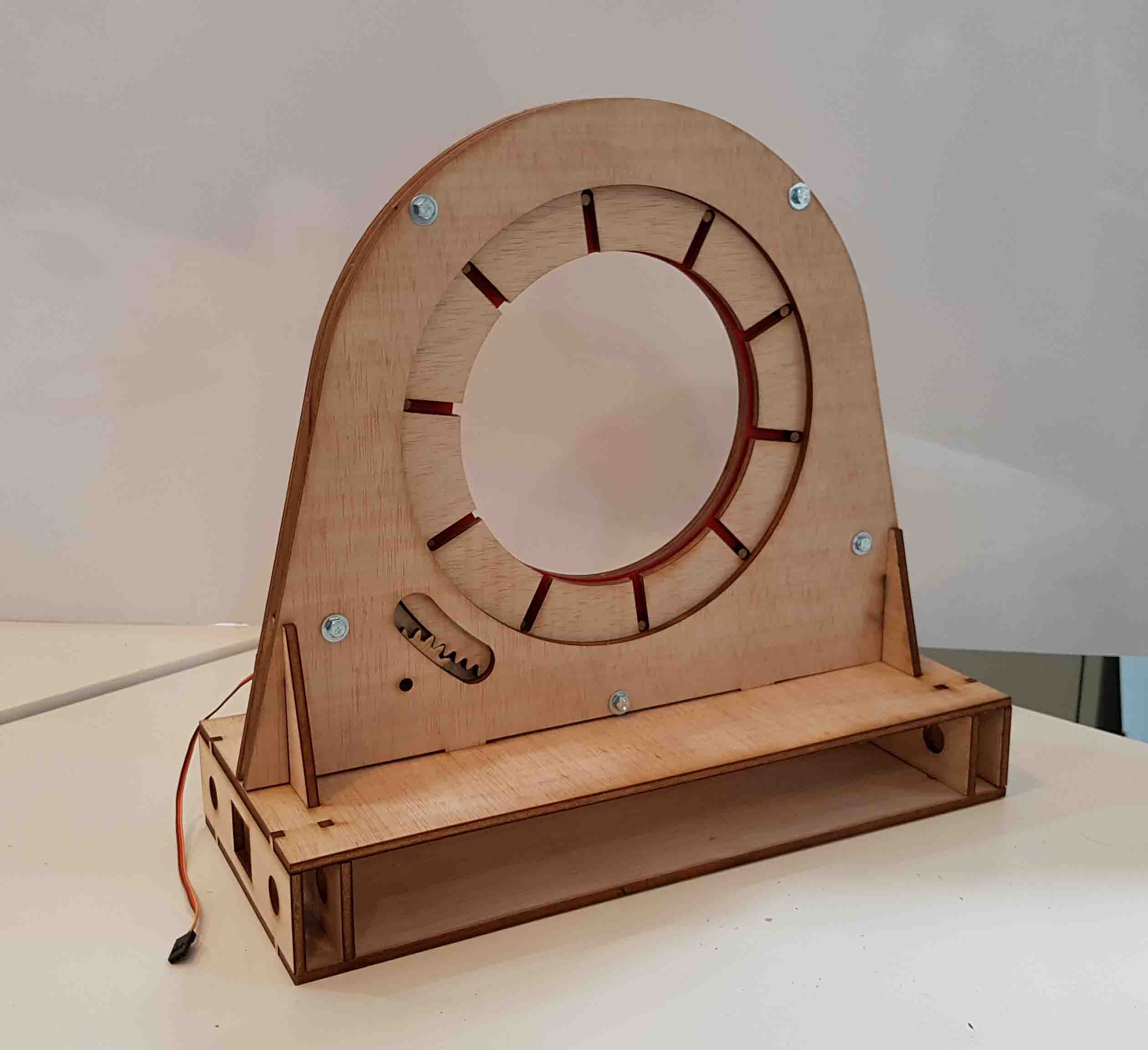
I'll model the iris part in Rhino. The iris consists of two exterior pieces (orange) that hold everything together. The iris blades (red) have a pin (blue) glued in both of its ends, one looking up and one looking down. One pin is inserted in the hole of the fixed case (orange), while the other pin is inserted in the actuator ring (green). The blue ring gives enough space for the blades and the blue half ring contains the actuator ring. Attached to the servo there is another little gear (green) that moves the whole actuator ring.

Assembly:

Notice how the actuator ring (green) only spins the right angle when opening (left) or closing (right) the iris in order to avoid opening or closing too much and breaking the mechanism:
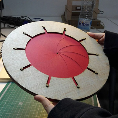
Thais designed the platform on top of which the iris will be assembled:

Some of the interior is not covered in order to be able to see how the mechanism works.

This time we used 5mm plywood. For the laser settings:
Cutting: Power 100, Speed 1. 1000Hz
Engraving: Power 20, Speed 3. 1000Hz

And let's start putting everything together

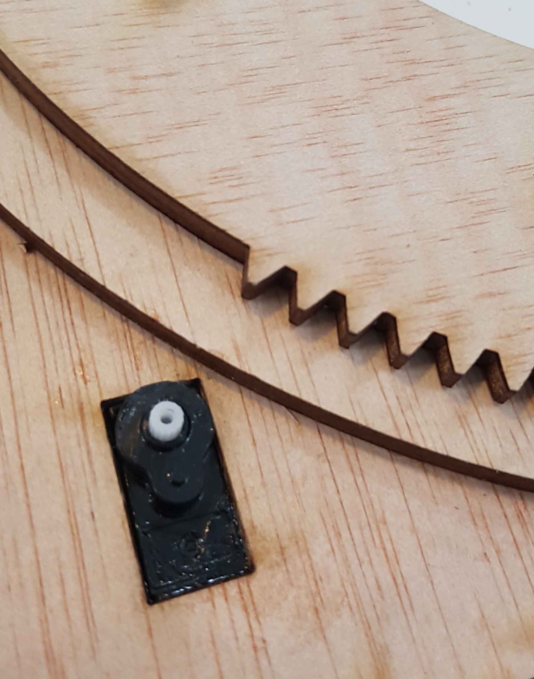
We made a gap to insert the servo motor where it is glued:
We were not sure if the actuator ring could spin smoothly. The friction with the wood makes the movement a bit hard.


Machine:
The iris worked fairly but some changes had to be done to the design.
First, we didn't know servo motors usually only spin 180 degrees, which was not enough for the servo attached gear to spin the actuator ring all the way. Which means the iris could not fully close. In order to fix this, the servo needed to be changed to a Continuous Rotation Servo (SM-S4303R), which luckily we had one in the lab. Continuous Rotation Servos are actually not standard servos because they cannot be commanded to go to a specific position and stop, and apparently there is no way arduino can tell what position it is at at any specific time, these servos have no feedback... What we have now is a variable speed bi-directional geared motor, not a servo. The explanation of why it is called a servo is that it starts life out as a complete standard servo, then they remove the internal geared feedback to the internal pot and also remove the mechanical end stops on the gear train, which then makes it a variable speed bi-directional geared motor drive. However we'll keep calling it 'servo'.
This new servo is bigger and stronger, which will be better to spin the actuator ring. That also means the hole designed for the motor changed. Some pieces were cut to make a frame for the motor so it is better fixed to the iris frame.
Second, the actuator ring had a lot of friction with the rest of the frame. Some changes were made for this:
-changing the actuator ring from 5mm to 3mm plywood
-reducing the quantity of surface in contact with the frame.
-sanding the edge of the pieces seems to improve the movement. The laser browned edges seem more sticky than the original wood texture and the actuator ring sometimes got stuck and forced the servo motor.
Third, the press-fit assembly for the iris to the platform was too far on the side, which made the wood weak and easy to break. To solve this, the slots were moved more to the interior.
Everything seems to be correct now, so it is time or the assembly of the new iris. Before closing the whole mechanism, we tried to program the servo and see its response. However it is not responding how it should, it moves in a weird way and stops unexpectedly. Finally we found out the problem is that the servo is not calibrated, and thats what we are gonna do now.
For the calibration we will use this code:
  #include < Servo.h >
  Servo servoRotCont;

  void setup() {

    servoRotCont.attach(9);


  }
  void loop() {
    servoRotCont.write(90);// STOP

  }
After running this code, the servo motor should be completely stopped. If it is moving, it means the motor is not calibrated. The result was this:
It is moving, which means it is not calibrated. To calibrate it we need to introduce the screwdriver in the hole that access the potentiometer and rotate it. One direction makes it move faster and the other slows it down. We rotated it until it stopped.
Now the servo is calibrated and it can be programmed correctly. But a continuous rotation servo doesn't work in the same way as a standard servo: you can't choose the angle you want it to rotate to, but you can choose the direction of rotation, the speed and the time (delay). This is not as precise as a standard servo because you can't choose the desired angle, this needs to be achieved with these other three settings. However this is tricky: For example, to move the actuator ring gear all the way (30 teeth) means moving the servo gear (20 teeth) one and a half turns (20teeth*1.5=30teeth). This would be easy if we could program de motor to rotate 360+180 degrees but we can't do it this way. You need to set a direction and a speed and calculate the time it takes to rotate the desired angle. Not only this is not precise at all but you also need to consider that the motor gear doesn't rotate at the same speed when completely free as when there is some resistance (the actuator ring gear). This means different delay time for the same angle depending on the resistance and also the orientation of the gear (it doesn't rotate the same speed when horizontal than when it is vertical, because the weight of the actuator ring also slows down the motor gear). So, we decided to assemble everything and orient the iris vertically, because this is how the machine will finally be. And THEN, you can start playing with the correct rotation time.
So far, we decided to:
-Close the iris completely
-Open the iris completely
-Close the iris to position 1
-Close the iris to position 2
-Close the iris to position 3
-Open the iris completely
Between each movement there is a stop.
And after testing, the result was this:
-Close the iris completely (2400 milliseconds)
-Open the iris completely (2400 milliseconds)
-Close the iris to position 1 (650 milliseconds)
-Close the iris to position 2 (650 milliseconds)
-Close the iris to position 3 (650 milliseconds)
-Open the iris completely (2400 milliseconds)
Closing the iris to each position should be the total closing time (2400 milliseconds) divided by three (2400/3=800 milliseconds). However for some reason it doesn't work like this and 650 milliseconds for every step seems to work better. If only the angle could be chosen it would be much more precise.
This is the code used to program the iris:
  #include < Servo.h >
  Servo servoRotCont; // crea los objetos para controlar los servomotores

  void setup() {
    servoRotCont.attach(9);
  }
  void loop() {
    servoRotCont.write(0);//close
    delay(2400);
    servoRotCont.write(90);//stop
    delay(2000);
    servoRotCont.write(180);//open
    delay(2400);
    servoRotCont.write(90);//stop
    delay(2000);
    servoRotCont.write(0);//close to 1
    delay(650);
    servoRotCont.write(90);//stop
    delay(2000);
    servoRotCont.write(0);//close to 2
    delay(650);
    servoRotCont.write(90);//stop
    delay(2000);
    servoRotCont.write(0);//close to 3
    delay(800);
    servoRotCont.write(90);//stop
    delay(2000);
    servoRotCont.write(180);//open
    delay(2400);
    servoRotCont.write(90);//stop
    delay(2000);
  }
Now it's time to program the stepper motor. What is a stepper motor?
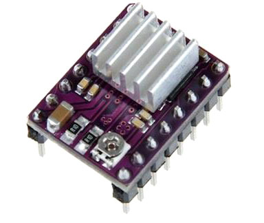
To do that we will use the DRV8825 Stepper Motor Driver Carrier.
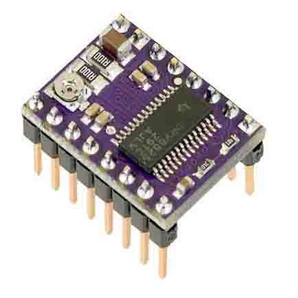
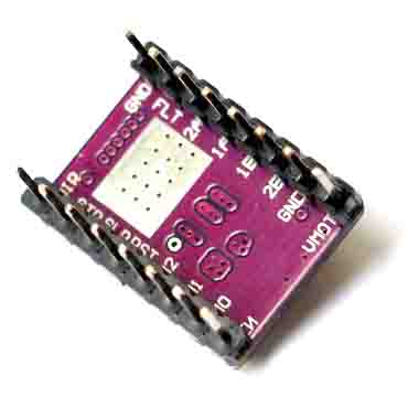
When running, the driver gets extremely hot. For this reason it comes with a heatsink that is stuck to the microcontroller to dissipate the heat, like this:
Arduino has a shield compatible with these drivers, the CNC shield:
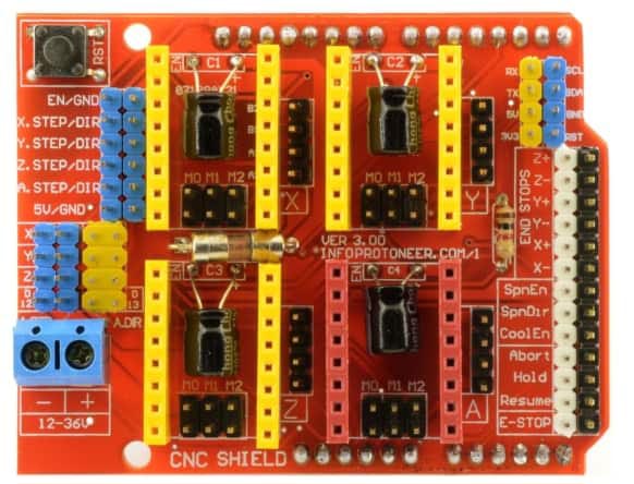
This shield goes on top of the Arduino board and connects the arduino to the driver, like this:

However, after assembling everything and uploading some code to Arduino, the motor was not working very well. The motor made some noise but it didn't move. Tried rotating the potentiometer in the driver with a screwdriver but the motor still didn't move.
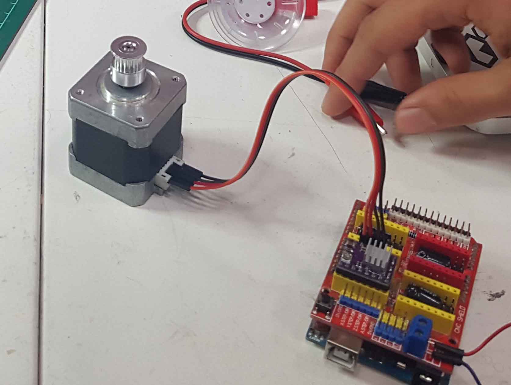
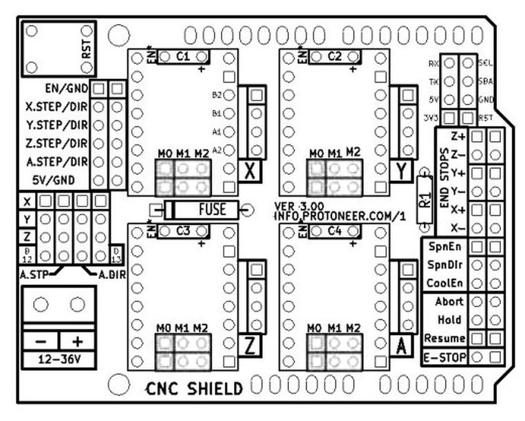
Mikel suggested the CNC shield was not working well and we made all the connections between Arduino and the driver using jumpers and a protoboard. The good thing about this is that we now understand better the driver pinout.
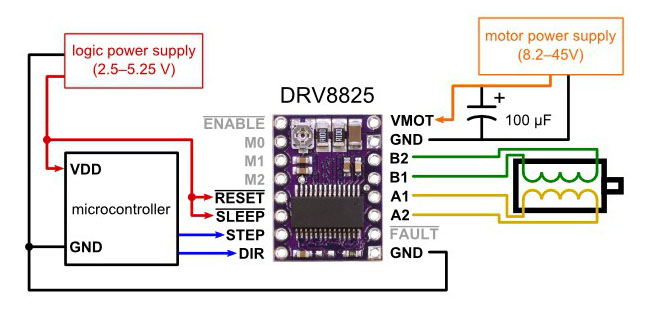
A1 and A2 (yellow) are connected to one of the coils in the stepper motor (first and third pin). B1 and B2 (green) are connected to the other coil (fourth and sixth pin). There are two pins in the stepper motor that are not used.


This time the motor was still not moving but it made a better sound than before. We struggled a little bit with the code for the stepper motor. Mikel wrote a code to see if it was working correctly. Rotating the potentiometer in the driver made it finally work (the potentiometer is very sensitive, and a very little rotation will make it work or not). Now that we knew everything was working perfectly, we tried to understand the code and write it ourselves. Our code didn't work...some of the delay functions were in microseconds (delayMicroseconds) when it had to be in milliseconds (delay). Fixing this finally made it work.
  byte dirPin = 7;
  byte stepPin = 6;
  int steps = 4900;
  int stepDelay = 2;


  void setup() {

    Serial.begin(9600);
    Serial.println("Setup");
    pinMode(dirPin, OUTPUT);
    pinMode(stepPin, OUTPUT);
    digitalWrite(dirPin, HIGH);
  }

  void loop() {
    //Activar una direccion y fijar la velocidad con stepDelay
    digitalWrite(dirPin, HIGH);


    Serial.println("DIR1");
    for (int n = 0; n < steps; n++) {
      digitalWrite(stepPin, HIGH);
      delayMicroseconds(stepDelay);
      digitalWrite(stepPin, LOW);
      delay(stepDelay);
      //Serial.println(n);
    }

    delay(500);

    //Cambiamos la direccion y aumentamos la velocidad
    digitalWrite(dirPin, LOW);
    //stepDelay = 2;

    Serial.println("DIR2");
    for (int x = 0; x < steps; x++) {
      digitalWrite(stepPin, HIGH);

      delayMicroseconds(stepDelay);
      digitalWrite(stepPin, LOW);
      delay (stepDelay);
      // Serial.println(x);

    }
    delay(500);
  }
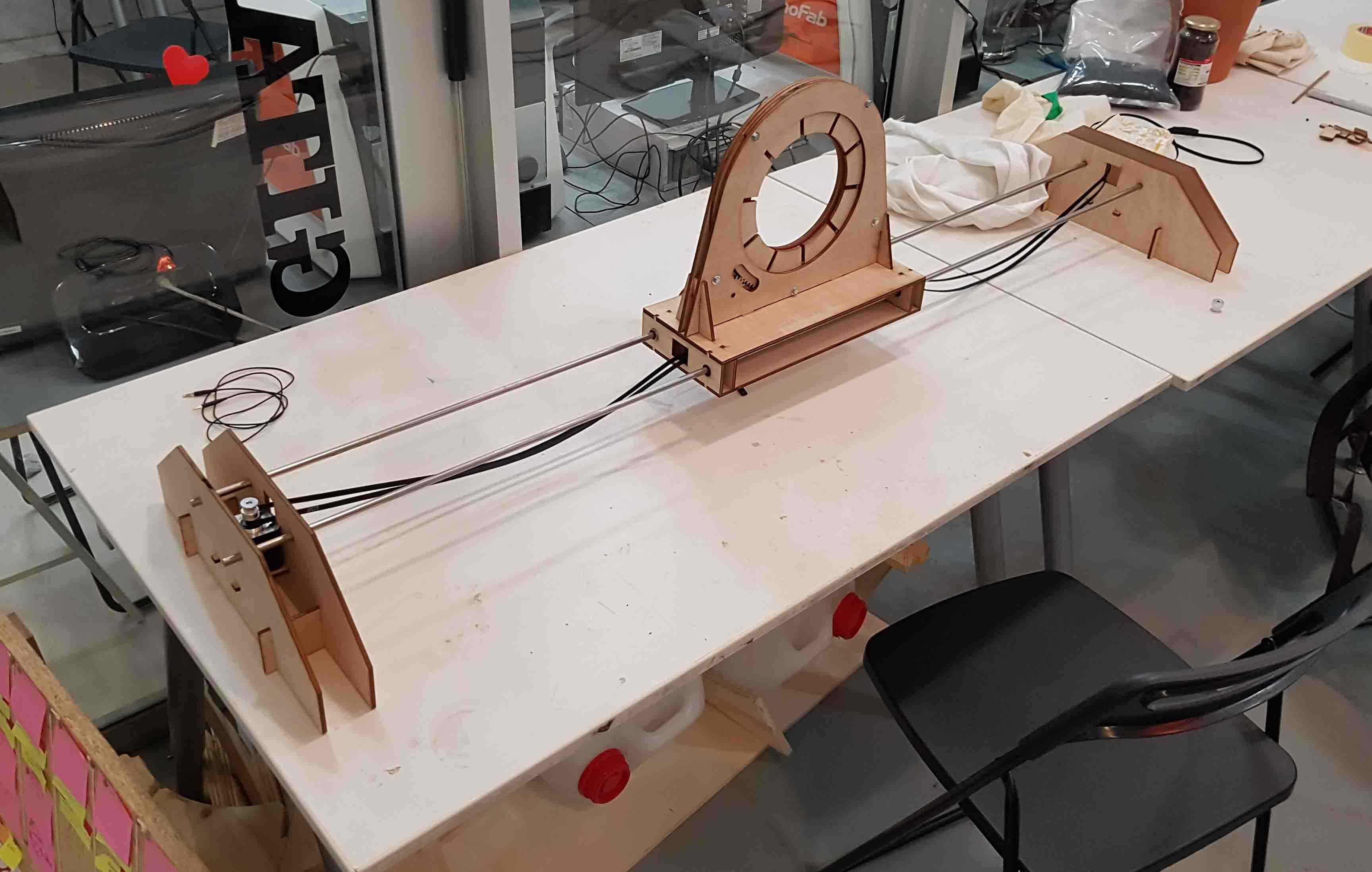
Time to assemble the whole machine and test it. The belt needs to be tight, otherwise it will not grab the pulleys correctly.
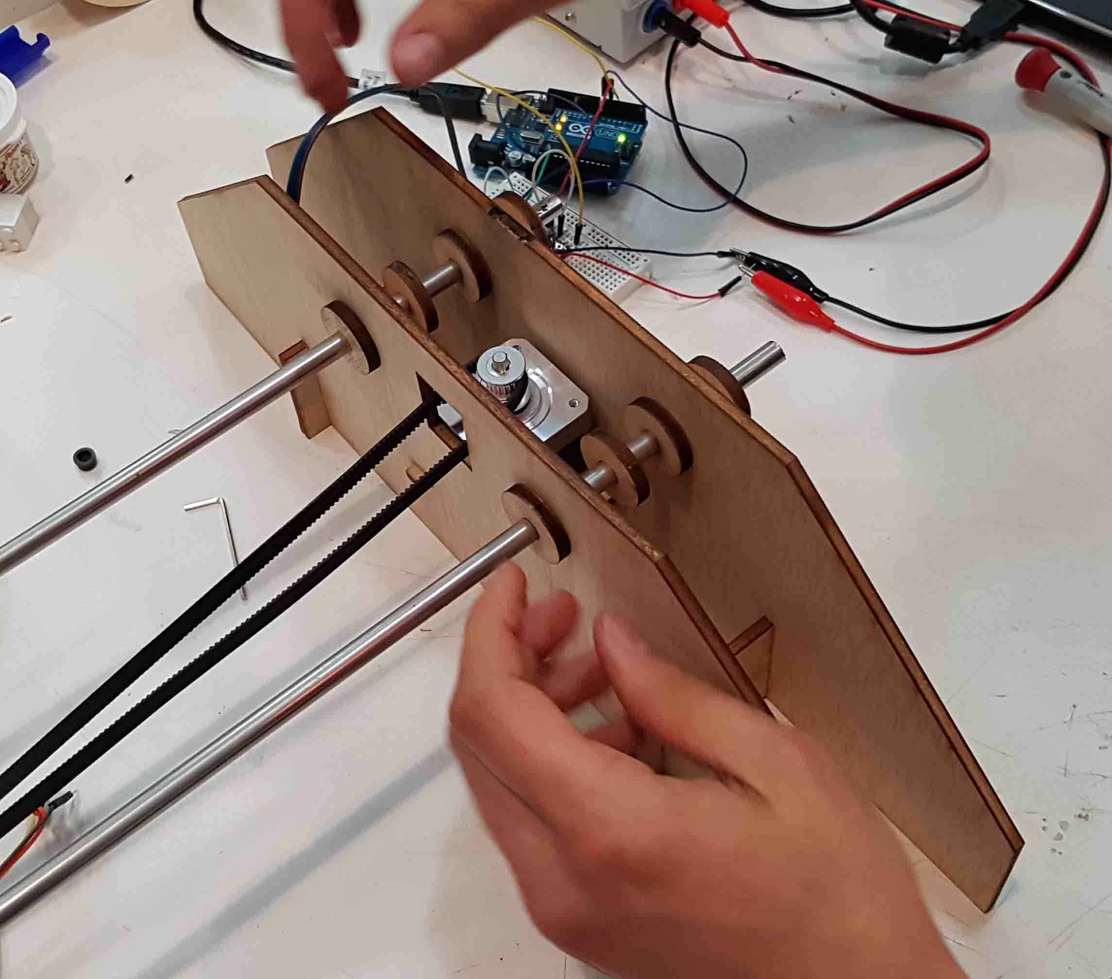
The code we uploaded is a loop to spin the motor one direction and then spin it the same steps on the other direction, so the platform can go from one side to the other side of the machine. To know how many steps it needs we did it by trial. We didn't use and endstop, , we started checking small number of steps for the stepper motor and gradually increased the number of steps until it moved the platform the whole way from one side to the other. We did have a few tries beyond the mechanical limits. However, this didn't damage the setup, as the belt slipped from the pulley when the platform hit the limit. 1000 steps made the platform move around 20%, so we kept increasing this number until it reached the other side. 4900 steps seemed ok to move the platform along all the railings.
Time to play with it!

This work is licensed under a Creative Commons Attribution-NonCommercial-ShareAlike 4.0 International License.