week 12 - interface & application programming
-individual assignment: write an application that interfaces with an input &/or output device that you made
-group assignment: compare as many tool options as possible
This week I'll test the serial communication between one of my boards and Processing.
Processing is a programming language designed for the visual arts community. It is open source and uses basic syntax for creating drawings, animations, and interactive programs. It also includes a basic IDE, which serves as the programming interface. The Processing language and IDE were the precursor to other projects such us Arduino, so that's why they are pretty similar in syntax. You can learn a lot of Processing coding from watching Daniel Shiffman's guides.
I will use Serial Communication between our micro-controllers and our computers using the FTDI cable via the Universal Serial Bus (USB). Most programming languages have Serial libraries that allow you to talk directly via the serial port of your computer (USB is one of many serial protocols). Processing and Arduino also have their respective serial libraries. This tutorial is pretty helpul. Also this video explains it pretty well:
I decided to connect my board from week 6, which has a Button and a LED, to Processing. For the communication, Pin0 will be my RX and Pin1 will be my TX. Remember the microcontroller's RX goes to the cable's TX, and the the microcontroller's TX goes to the cable's RX, as seen below:
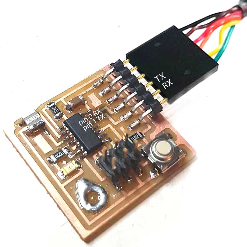
From ATtiny...
First I will make the board send data to Processing. In Arduino, we first need to include the SoftwareSerial library to run serial on Attiny44, declare our serial ports, and declare our button and LED pin numbers.
// Include the SoftwareSerial library to run serial on Attiny44
#include < SoftwareSerial.h >

// declare my serial ports 0 and 1 (RX, TX)
SoftwareSerial mySerial(0, 1);

int buttonPin = 3;   // the number of the pushbutton pin
int ledPin =  7;     // the number of the LED pin
int buttonState = 0; // variable for reading the pushbutton status
In the setup, we need to set the the data rate in bits per second (baud). This needs to be the same both in the ATtiny and in Processing, oherwise the communication will not work properly.
void setup() {
  mySerial.begin(115200); // set baud rate to 115200 bits per second
  pinMode(buttonPin, INPUT);
  pinMode(ledPin, OUTPUT);
In the loop, we will send a 1 when the button is pressed and a 2 when the button is not pressed. These will be read by Processing in order to make something. The mySerial.print function allows to see the SensorValue in the Arduino serial monitor, which is good to check before moving on to Processing.
void loop() {
  buttonState = digitalRead(buttonPin);
  if (buttonState == 0) {
    digitalWrite(ledPin, HIGH);
    mySerial.write(1);
    //mySerial.println("pressed");
  } else {
    digitalWrite(ledPin, LOW);
    mySerial.write(2);
    //mySerial.println("not pressed");
  }
}
Then we load all this code into our board with the AVRISP programmer.
...to Processing
Now, in Processing, we need to listen what our ATtiny is sending. First we need to import the Serial Library and declare some variables:
import processing.serial.*; //import serial library
In order to listen to any serial communication we have to get a Serial object (we'll call it myPort), which lets us listen in on a serial port on our computer for any incoming data. We also need a variable to recieve the actual data coming in.
Serial myPort;  // Create object from Serial class
int val;      // Data received from the serial port
For our setup() method in Processing, we're going to find the serial port our Arduino is connected to and set up our Serial object to listen to that port. With the function printArray(Serial.list()); we can figure out which USB port our ATTiny is sending its data through, in my case [0].
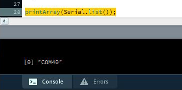
Once we know our port number, we'll define the setup() like this. (Remember to set the same baud rate as in Arduino!)
void setup()
{
  size(500, 500);
  String portName = Serial.list()[0];
  //printArray(Serial.list());
  myPort = new Serial(this, portName, 115200); // Set baud rate equal to microprocessor
}
In our draw() loop, which is similar to Arduino's loop(), we're going to listen in on our Serial port and get something, stick that something in our val variable and print it so we know if the data is received correctly. If instead of receiving 1s or 2s we are receiving other characters or other numbers, we might have to check if we are sendint data as int, char, string...etc so we should read it in Processing the same way.
As for the interface, I first tried something simple. In the Processing display window, if the data read by the port is 1 (board button is pressed), it will paint a square in black. If the read data is 2 (board button is not pressed), it will paint a square in grey.
void draw()
{
  while ( myPort.available() > 0) {  // If data is available,
    val = myPort.read();   // read it and store it in val
    println(val);
  }
  background(255);             // Set background to white
  if (val == 1) {              // If the serial value is 0,
    fill(0);                   // set fill to black
  }
  else {                       // If the serial value is not 0,
    fill(204);                 // set fill to light gray
  }
  rect(50, 50, 100, 100);
}
And here is the result!
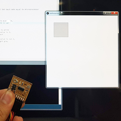
button not pressed = square painted in grey
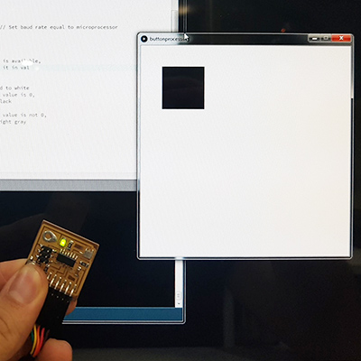
button pressed = square painted in black
Here are the two complete codes I used:
import processing.serial.*; //import serial library
Serial myPort;  // Create object from Serial class
int val;      // Data received from the serial port

void setup()
{
  size(500, 500);
  String portName = Serial.list()[0];
  //printArray(Serial.list());
  myPort = new Serial(this, portName, 115200);
  // Set baud rate equal to microprocessor
}

void draw()
{
  while ( myPort.available() > 0) {  // If data is available,
    val = myPort.read();   // read it and store it in val
    println(val);
  }
  background(255);             // Set background to white
  if (val == 1) {              // If the serial value is 0,
    fill(0);                   // set fill to black
  }
  else {                       // If the serial value is not 0,
    fill(204);                 // set fill to light gray
  }
  rect(50, 50, 100, 100);
}
// Include the SoftwareSerial library to run serial on Attiny44
#include < SoftwareSerial.h >

// declare my serial ports 0 and 1 (RX, TX)
SoftwareSerial mySerial(0, 1);

int buttonPin = 3;   // the number of the pushbutton pin
int ledPin =  7;     // the number of the LED pin
int buttonState = 0; // variable for reading the pushbutton status

void setup() {
  mySerial.begin(115200); // set baud rate to 115200 bits per second
  pinMode(buttonPin, INPUT);
  pinMode(ledPin, OUTPUT);

}

void loop() {
  buttonState = digitalRead(buttonPin);
  if (buttonState == 0) {
    digitalWrite(ledPin, HIGH);
    mySerial.write(1);
    //mySerial.println("pressed");
  } else {
    digitalWrite(ledPin, LOW);
    mySerial.write(2);
    //mySerial.println("not pressed");
  }
}
But this interface is pretty boring. Now that I know everything is working fine, I'll move on trying something more fun. I wanted to try some of the Processing sketches I have been doing lately. I made this one when learning how to use GIFs in Processing. You can find the code below (you will need the data folder containing all the GIF .png frames inside the processing sketch folder, you can find the files here).
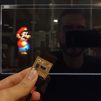
button not pressed = Mario stops
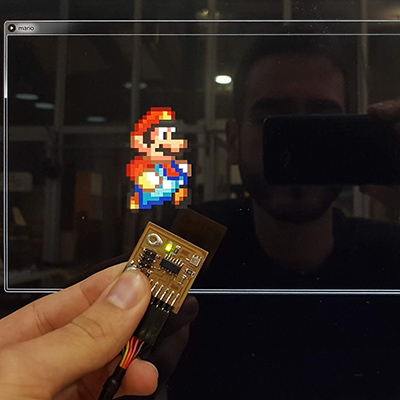
button pressed = Mario walks
(you will need the data folder with the GIF frames!)
  int i=3;
  PImage[] mario = new PImage[i];
  float x;

  import processing.serial.*; //import serial library
  Serial myPort;  // Create object from Serial class
  int val;      // Data received from the serial port

  void setup() {
    size (1800, 500);
    mario [0]= loadImage("mario0.png");
    mario [1]= loadImage("mario1.png");
    mario [2]= loadImage("mario2.png");
    frameRate(15);
    x=width/10;
    background(0);
    imageMode(CENTER);
    image(mario[0], x, height/2);

    String portName = Serial.list()[0];
    //printArray(Serial.list());
    myPort = new Serial(this, portName, 115200); // Set baud rate equal to microprocessor
  }
  void draw() {

    while ( myPort.available() > 0) {  // If data is available,
      val = myPort.read();   // read it and store it in val
      println(val);
    }

    if (val == 1) {
      x=x+10;
      background(0);
      image(mario[frameCount%3], x, height/2);
    }

    else {
      background(0);
      image(mario[0], x, height/2);
    }

  }
// Include the SoftwareSerial library to run serial on Attiny44
#include < SoftwareSerial.h >

// declare my serial ports 0 and 1 (RX, TX)
SoftwareSerial mySerial(0, 1);

int buttonPin = 3;   // the number of the pushbutton pin
int ledPin =  7;     // the number of the LED pin
int buttonState = 0; // variable for reading the pushbutton status

void setup() {
  mySerial.begin(115200); // set baud rate to 115200 bits per second
  pinMode(buttonPin, INPUT);
  pinMode(ledPin, OUTPUT);

}

void loop() {
  buttonState = digitalRead(buttonPin);
  if (buttonState == 0) {
    digitalWrite(ledPin, HIGH);
    mySerial.write(1);
  } else {
    digitalWrite(ledPin, LOW);
    mySerial.write(2);
  }
}
From Processing to ATtiny
Alright! So I've sent data from the ATtiny to Processing, now I want to do it the other way, from Processing to the ATtiny. My board also has a LED so this will act as an output. I made a simple sketch with a black circle that turns green when the mouse is inside it. If the mouse is outside the circle, Processing will send a 1. If the mouse is outside, it will send a 0. Our ATtiny code will read this value, and if it is a 1, the LED will turn ON. Here the result:
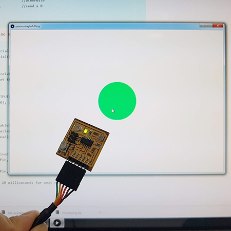
mouse inside the circle = led on
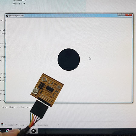
mouse outside the circle = led off
  float xe, ye, rad;
  color ce;

  import processing.serial.*; //import serial library
  Serial myPort;  // Create object from Serial class
  int val;  // Data received from the serial port

  void setup() {
    size(900, 600);
    background(255);

    rectMode(CENTER);
    ellipseMode(RADIUS);
    noStroke();

    rad = 80;
    xe = width/2;
    ye = height/2;
    ce = color(255, 0, 150);

    String portName = Serial.list()[0];
    //printArray(Serial.list());
    myPort = new Serial(this, portName, 115200);
    // Set baud rate equal to microprocessor
  }

  void draw() {
    background(255);
    fill(ce);
    ellipse(xe, ye, rad, rad);
    // if the mouse is inside
    if (dist(xe, ye, mouseX, mouseY) < rad) {
      ce=color(0, 255, 100);
      myPort.write(1);
    } else {
      // if the mouse is outside
      ce=color(0, 0, 0);
      myPort.write(0);
    }
  }
  // Include the SoftwareSerial library to run serial on Attiny44
  #include < SoftwareSerial.h >

  // declare my serial ports 0 and 1 (RX, TX)
  SoftwareSerial mySerial(0, 1);

  int ledPin =  7;      //the number of the LED pin
  char val; // Data received from the serial port

  void setup() {
    mySerial.begin(115200); //set baud rate to 115200 bits per second
    pinMode(ledPin, OUTPUT);
  }

  void loop() {
     if (mySerial.available())
    { // If data is available to read,
      val = mySerial.read(); // read it and store it in val
    }
    if (val == 1) {
      digitalWrite(ledPin, HIGH);
    } else {
      digitalWrite(ledPin, LOW);
    }
  }
So far I made my ATtiny board and Processing communicate via serial when one is talking and the other is listening and also the other way around. You can also make a link that allows data to flow both ways, so that ATtiny and Processing are both sending and receiving data. This is called a serial ‘handshake', since both sides have to agree when to send and receive data. I will not do it for this assignment, but you can check this tutorial here.
download files
This work is licensed under a Creative Commons Attribution-NonCommercial-ShareAlike 4.0 International License.