Week 15: Machine design (group assignment)
This week we followed the machine design class. You can see video here.
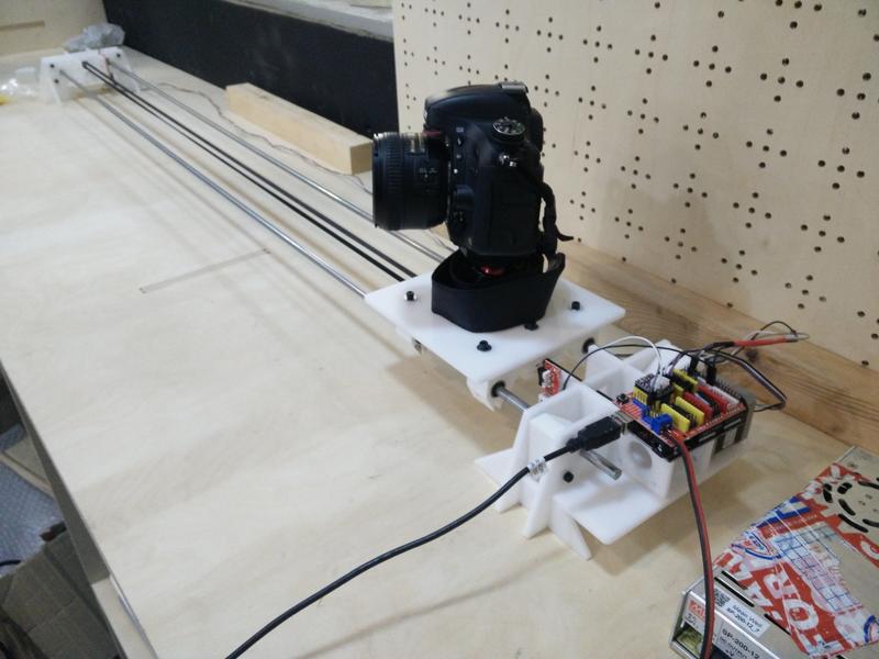
For this assignment we decided to build a camera time-lapse dolly! :)
This page is about the 1st part of the process in the group comprised by: Ilias Bartolini, Marta Bocos, André Pulcino, Óscar González
In this week I in particular contributed to:
- Cableing and power source tests
- Initial simple control of a step motor and testing it on the machine
- Designing and adding the endstop sensors solution (related firmware changes was done by Oscar)
- Camera header integration
- Final test videos with camera
See full the documentation on the group website.
Below is part of the documentation for the part that I directly contributed to in my group:
- Using a stepper motor
- Testing the motor on our machine
- Adding endstops
- Final result
- Lessons learned
- Next steps
Using a stepper motor
First simple example we took ad Arduino CNC shield with a DRV8825 stepper motor driver.
A good introductory guide to have our example working is this.
Documentation for the DRV8825 features and pinout is available here.
Documentation for the Arduino CNC shiled is available here.
The DRV8825 driver allow for various step resolution which can be configured via the jumpers on the CNC shield: 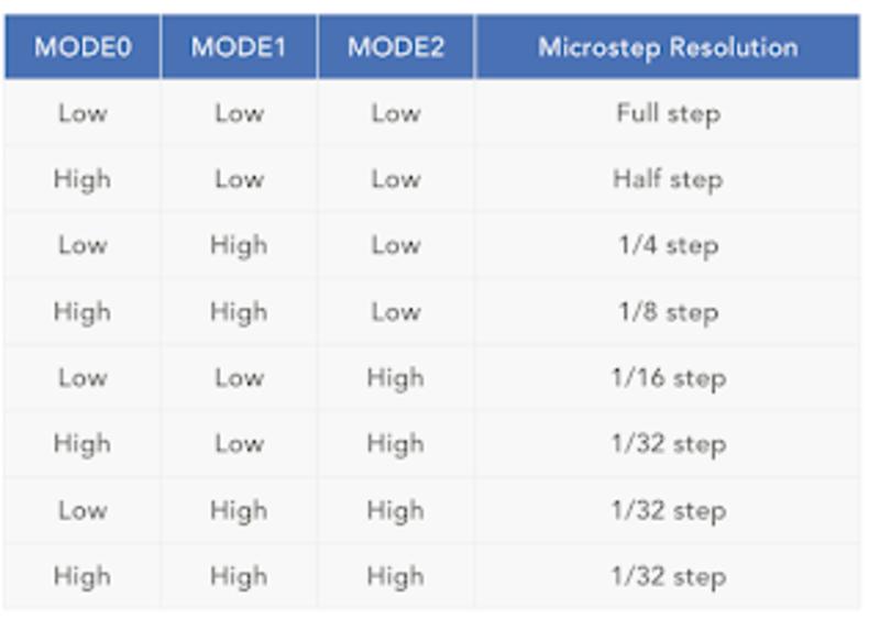
We picked the higher resolution and then tested with the sample code from the tutorial modified as below:
#define EN        8
//Direction pin
#define X_DIR     5
//Step pin
#define X_STP     2
//DRV8825
int delayTime=3200; //Delay between each pause (uS)
int steps=6400;// Steps to move

void move(boolean dir, byte dirPin, byte stepperPin, int steps)
{
  digitalWrite(dirPin, dir);
  delay(100);
  for (int i = 0; i < steps; i++) {
    digitalWrite(stepperPin, HIGH);
    delayMicroseconds(delayTime);
    digitalWrite(stepperPin, LOW);
    delayMicroseconds(delayTime);
  }
}

void setup(){
  pinMode(X_DIR, OUTPUT); pinMode(X_STP, OUTPUT);
  pinMode(EN, OUTPUT);
  digitalWrite(EN, LOW);
}

void loop(){
  move(false, X_DIR, X_STP, steps); //X, Clockwise
  delay(1000);
  move(true, X_DIR, X_STP, steps); //X, Counterclockwise
  delay(1000);
Here is the result.
Testing the motor on our machine
First of all we had to register the torque/current limit supplied to the motor by the stepper driver. The DRV8825 has a potentiometer which lets you regulate this setting. Later on I found this useful guide for this process.
After registering the current limit here is the functioning prototype assembled on our machine.
A little bit of adjustment was necessary to find the correct steps frequency and belt tension to avoid vibrations but still have a slow movement of the platform.
Adding endstops
We started thiking at different ways to add the endstops to the dolly structure and ended up with a simple glue solution :) 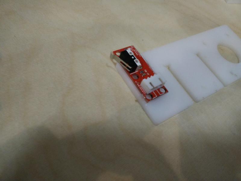
Here is the endstop assembled with the machine. 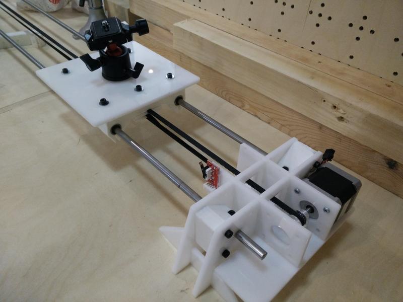
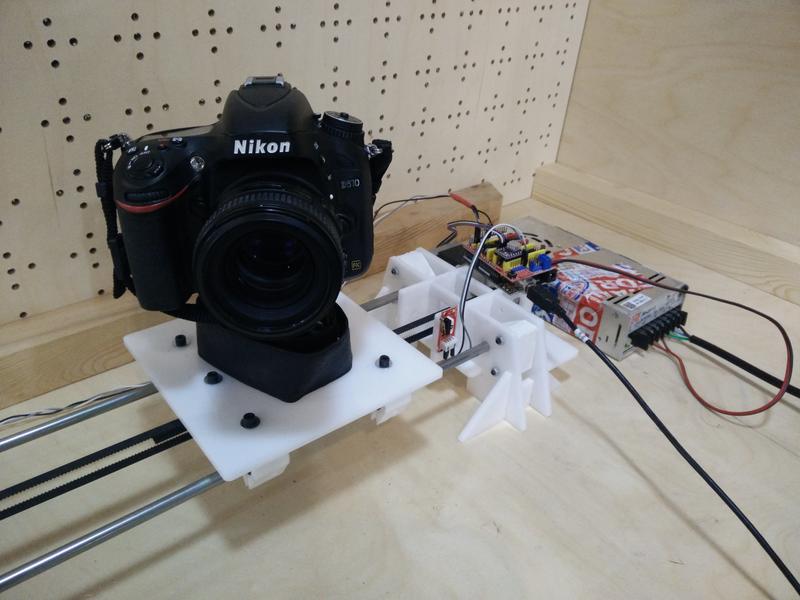
Final result
And now! The final result of our work!
And here a sample video of our Sloth time-lapse recording!!!
\o/ \o/
Summary slide and video! :)

Lessons learned
- How to drive a stepper motor! :)
- When we built our final structure, we made assumptions about the motor and drive mechanism: ideally we should be iterating on the mechanical structure once we learned about the components used.
- Driving a single motor is quite easy in code and we do not require a more complex CNC shield for this.
Next steps
- Add a speed control potentiometer.
- Optimize for battery powered components.
- Try smaller 5V stepper motor with gearing: eg. this.
- Try wiring the stepper driver without using the CNC shield.
- Design a better enclosure and wiring of the electronic parts.