Week 5: 3D printing
This week we followed the 3D scanning and printing class (see video here)
This page is about the individual assignment for designing a 3D printing part.
- Tux (RepRap - modify existing design)
- Screw (Formlabs - high resolution scan design)
- Ball bearing (RepRap - mechanical design)
Tux (RepRap - modify existing design)
Adapting the design (Blender)
I used for my design an adaptation of a Tux design from thingverse.
This part is difficult to create with a 3 axis milling machine because has holes and variations in diameter.
I decided to give another try to Blender for the pre-processing of the part. The goal is to remove defects and simplify it in a way that the need of external support in the print is minimized.
During the 2nd week I discarded it because I thought had a non intuitive interface but I decide to re-evaluate it because of the ‘3D printing’ Add-on. This time I approached it by taking the Blender Fundamentals youtube course first and I’ve been very happy with it!
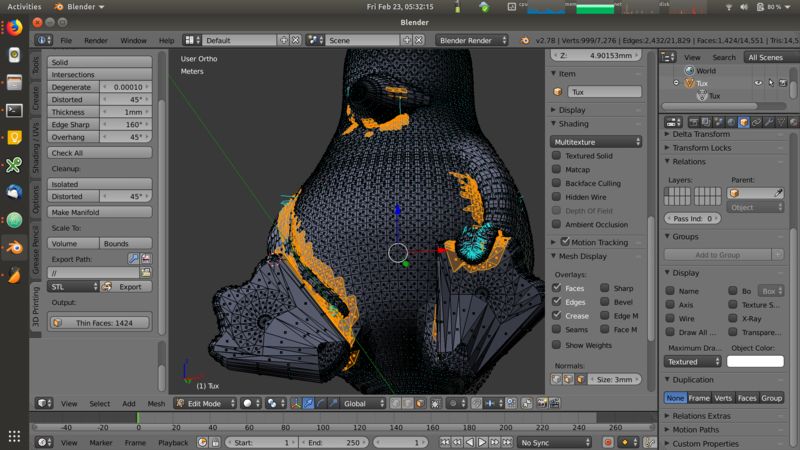
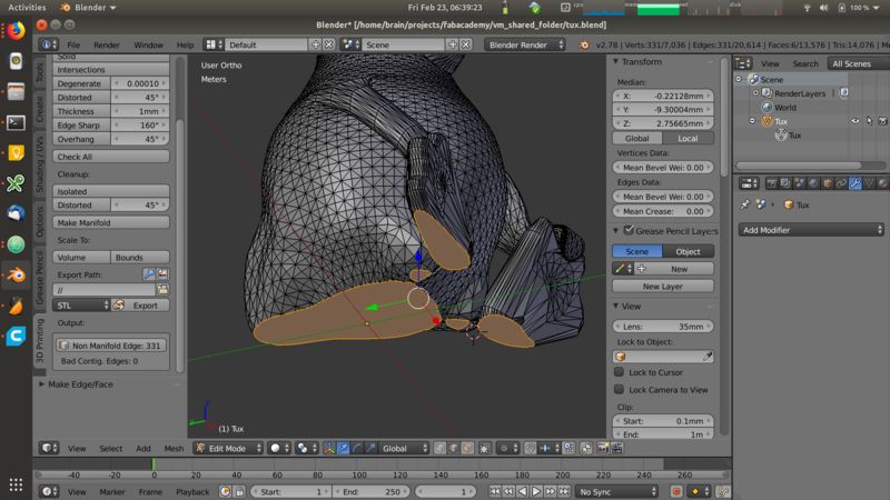
First I’ve fixed holes in the mesh:
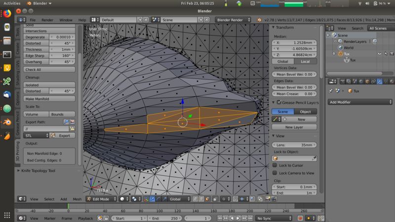
I removed intermediate layers and shortened the beek:
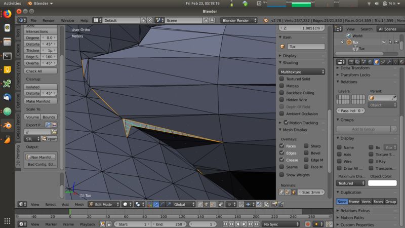
I checked sharp edges that might not be printed correctly:
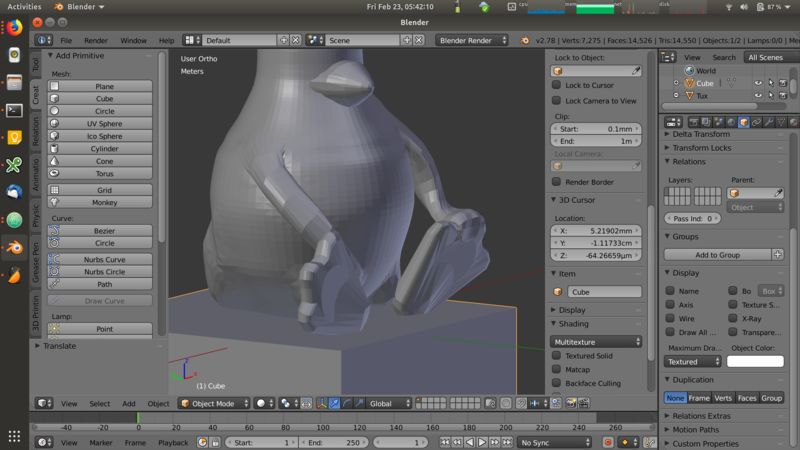
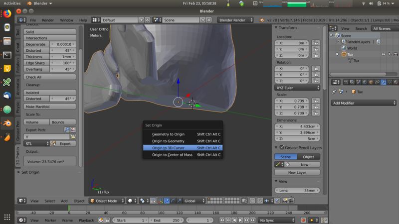
Finally I flattened the bottom and reset the origin position:
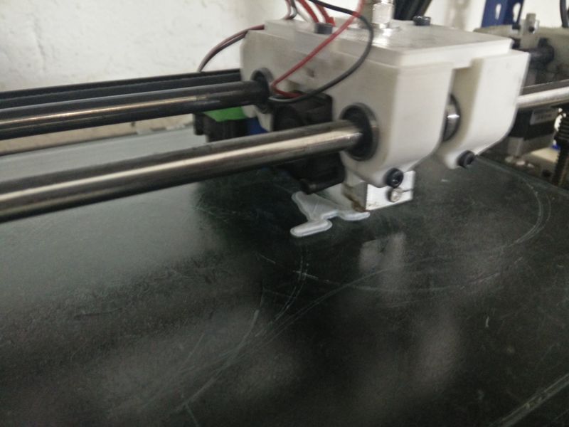
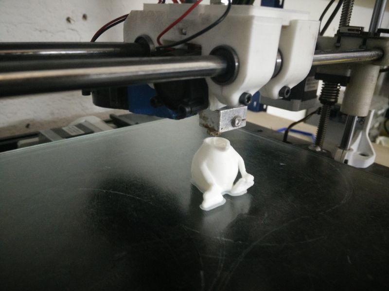
Printing
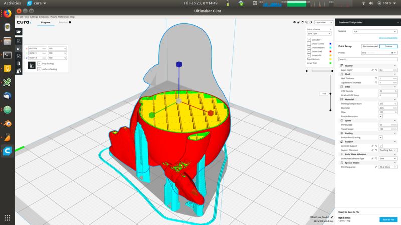
I prepared the print by using Cura (see the group assignment test for details)
I used mostly default parameters and checked the amount of support structured recommended by the program. Looking at the result I evaluated them to be minimal and I kept them out of the print job.
Once all the parameters are set, I generated the file as GCode and sent it to the machine via Octoprint
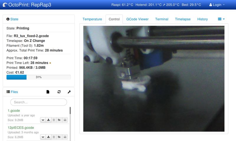
The printing process went smoothly and only in a couple of situations there have been minor itches.
Lessons learned
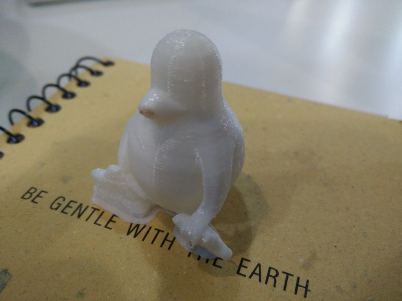
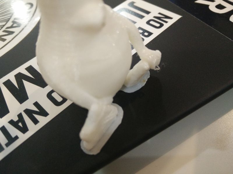
Two tiny defects were present on the model:
- The first is visible on the tip of the beek: during the print the thin surface started bending towards the top and the nozzle was scratching it leaving some dirty marks.
- The second defect is at the edge of the wing: in a form of a dangling filament. This is cuased by the lack of support structure in that protruding surface:
The overall process has been more smooth than expected!
Screw (Formlabs - high resolution scan design)
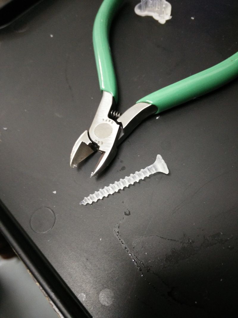
To test the Formlabs machine I used the design generated from the scan process with the roland machine. See more details here.
Printing
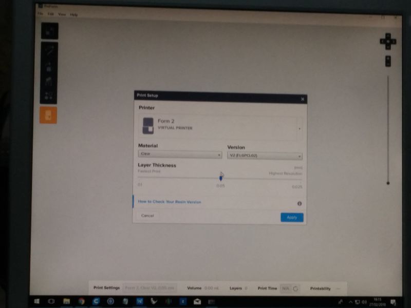
To setup the printing process we use the dedicated PreForm software.
Formlabs machine uses resins cartridges as printing material. When starting the process we need to choose the material with the exact code from the cartridges.
We also need to to setup the layer thickness that we desire. In my case the screw scan had a resolution of 0.1mm so we went for a resolution immediately below to not lose detail: 0.05mm.
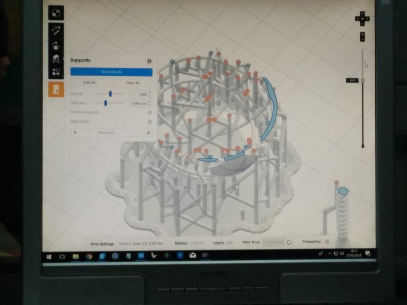
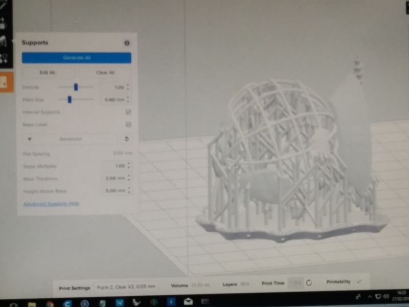
The software has the usual controls to place, rotate and resize parts.
It also has a “Printability” check that does not allow to start the print usless all requirements are met. In our example we had to add more support points on the structure.
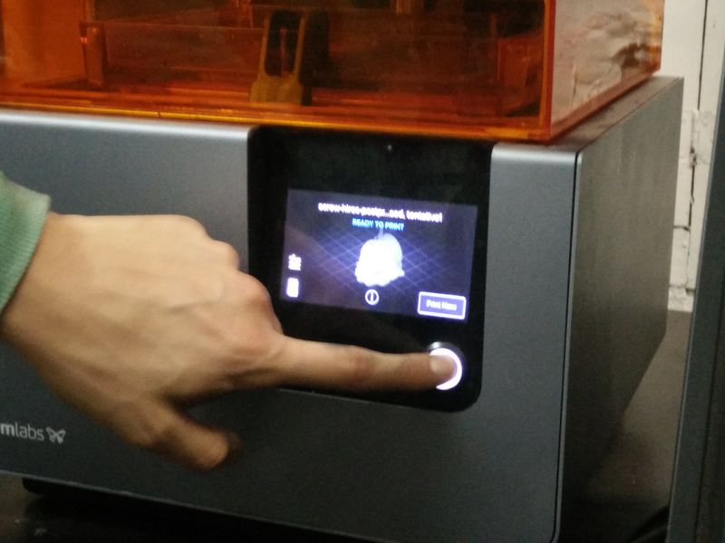
When everything is setup the printing job is sent to the machine which is wireless connected. Before starting we need to manually open the cartridge and start the process.
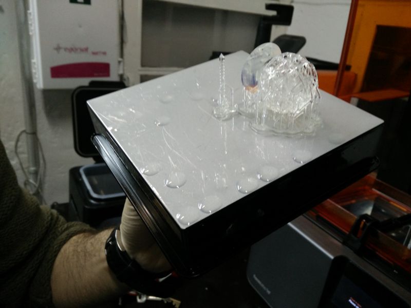
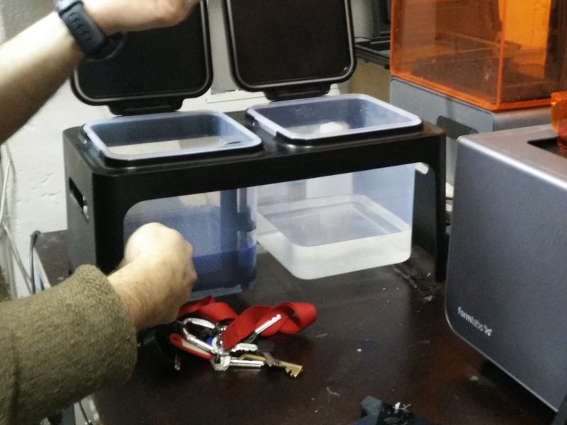
After removing the print from the surface the part need to be put in a cleaning bath of alchool and then water to remove resins residual.
We can postprocess the resins under UV light to add resistance to the material.
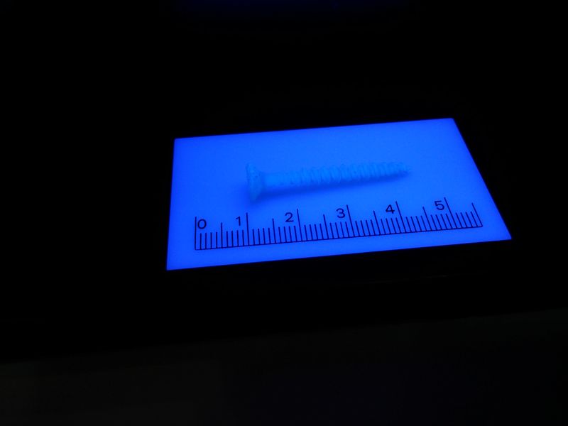
And here is the final result!
Lessons learned
- Stereolithography (SLA) process is much slower for designs that have mamy layers compared to a 3-axis extrusion machine. On the other side generating a complex single layer is very fast. The quality result are much higher than with extrusion machines.
- The SLA machine is very delicate and sensitive to dust or scratches of the printing surface. Always keep the lid close and be very careful when removing the printed parts.
- The parts require claening and post-processing process that is also time consuming and generate more waste liquids.
- With flexible materials it is possible to do post-processing and get a desired level of flexibility based on the post-processing time.
Ball bearing (RepRap - mechanical design)
As a printing test I decided to try 3D print a mechanical structure as a ball bearing.
The initial intent is to build a platform to rotate objects for a better 3d scanning with kinect.
Design (Solidwork & Blender)
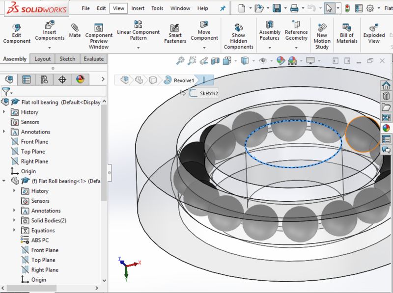
I thought that probably a simpler design to print could be a cylindrical roller bearing but I decided to give a try to the spherical one. Before printing the entire rotating platform I wanted to try a simple ball bearing element to verify the tolerances.
For this I used a parametric design in Solidworks.
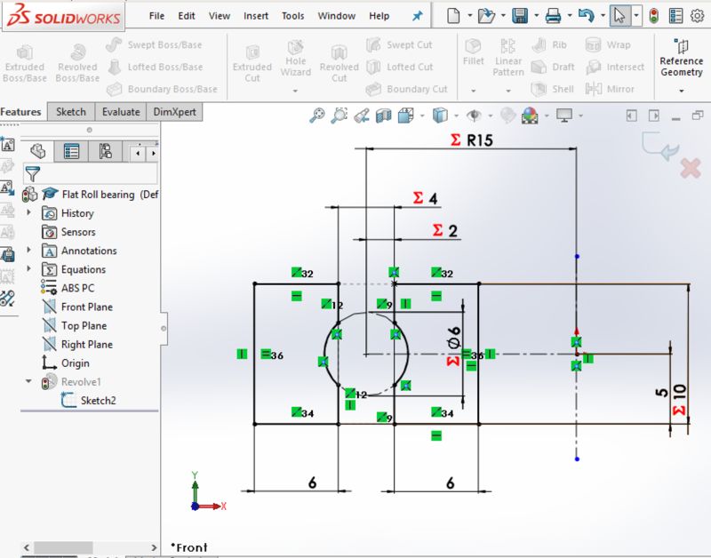
Download roll bearing design (.stl zipped - solidworks)
Blender has been useful later to check dimensions and reduce the number of polygons of the mesh.
Printing
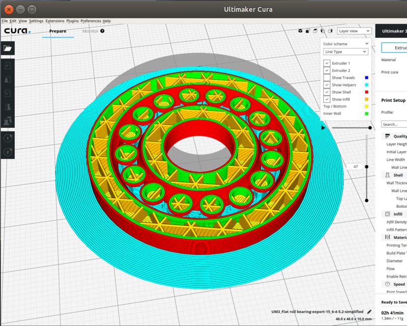
The process is identical at the one above. In Cura I just verified that the support for the spheres was present. I also added a bit of extra infill (25%) because the part is expected to have strong structural resistance to maintaint tolerances.
Here is the final result of the print.
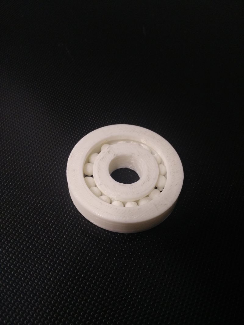
Lessons learned
- Because .stl files do not support units it is easy to mismatch in the process solidwork -> blender -> cura: double check your dimensions.
- The support for the spheres was probably a bit excessive, a bit difficult to remove and I can try to reduce it a bit.
- The roll bearing works better than expected with low attrition despite a bit wide tolerance. Next I could try reducing the tolerance from 1mm to 0.05mm changing the parameters in Solidworks and reprint it.
Happy 3D printing! ![]()