Week 3: Computer controlled cutting
This week we followed the computer cutting class (see video here)
This week we had two individual assignments for vinyl and laser cutting.
Vinyl cutting exercise
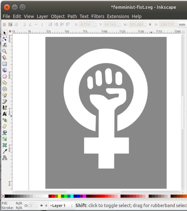
I decided to make a sticker with the vinyl cutter based on the common “femminist fist” logo but using the transgender symbol.
There are many images available but mostly in bitmap or photography formats.
I decided to start crating a custom vector path in inkscape overlapping an existing image and using transparency to draw on top the symbol.
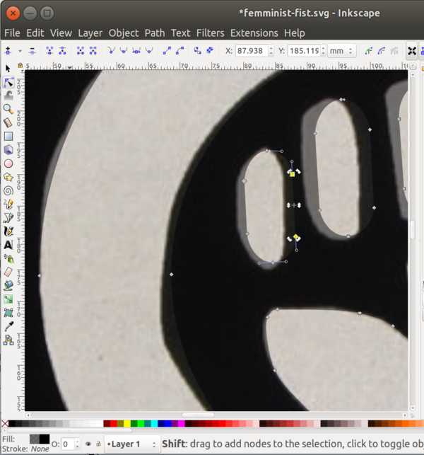
I ended up with the following .svg path:
Download source file (.svg)
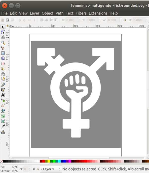
On top of the image above I then created the shape of the transgender symbol:
Download source file (.svg)
I used the files above with the Roland GS-24 vinyl cutter in our lab. A complete tutorial on how to use it is here
In our lab we had a roll of black vinyl material available for our tests.
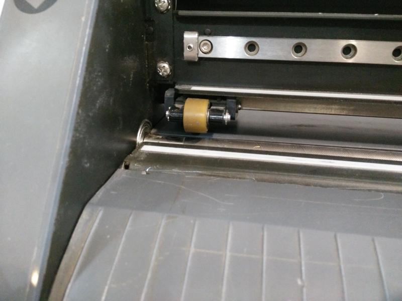
Before starting to cut I put the vinyl in the cutter. Pull down the blade on the back of the machine, align the material under the rubber wheels (the left one is fixed, but the left one can be moved) and pull the lever back when done.
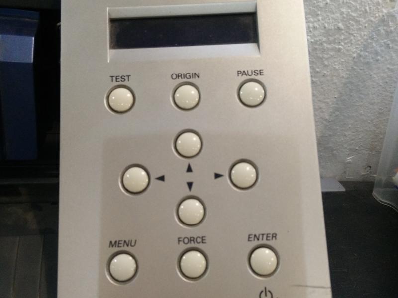
Using the side panel of the machine, after turining it up is possible to choose the type of roll and automatically measure it. The “SELECT SHEET” menu appears giving three options.
We can chose between “ROLL”, “PIECE” or “EDGE” pressing the arrows. By default, “PIECE” measures both the length and width of material. This is the one I choose: you can read the piece size from the screen. “ROLL” is the first option: this measures only the wheels width and finds the start of the roll (considering its length as indefinite). “EDGE” is similar to the “ROLL” except that they leave the knife in different position and it will measure the materil actual width.
Using the “TEST” button is then possible to print a sample shape like the one here (note: not my actual sample here):
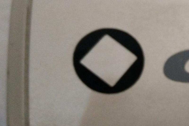
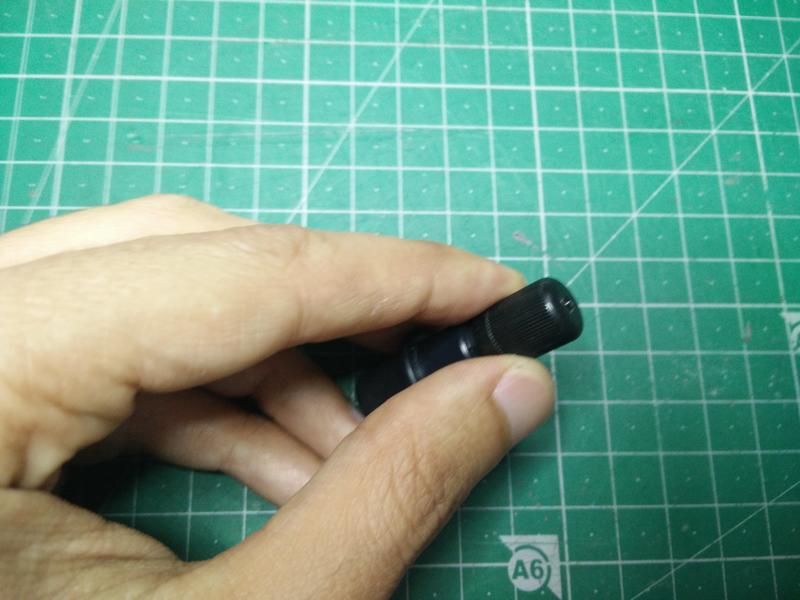
In case the material is not well defined or the blade is cutting through the support material. If not correct it is possible to adjust it rotating the blade cap (see picture) or adjusting the blade FORCE, SPEED or OFFSET from the panel menu.
To print the file is necessary to import the .svg image in the CutStudio software from Roland. I used a simple “cut and paste” from Inkscape to do that and resized it to fit in my vinyl sample that I measured earlier.
This is are two images in different sizes ready to print in CutStudio. 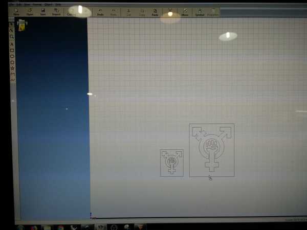
Press “Cutting” on the top of CutStudio. A print dialog will appear, Select the “Roland gx24”. Just click “Print” as a normal printer.
Remove the image from the roll using tweezers and apply it on the desider surface.
In my case the image was composed of a single piece. I designed it to be connected to simplify this process. In case an image is composed of multiple parts a transfer tape is needed as intermediate step.
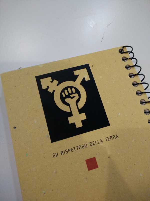
Here is the final stiker on my FabLab notepad! :)
Lessons learned
- I spent a lot of time creating a version of the file with rounded corners. I found out that it is not necessary. The vinyl sutter is capable to cut very sharp edges also for small dimensions.
I managed to print a version of the stiker where some of the thin paths are around 0.5mm. That section is very delicate but still does not break. - Range of importable file formats in CutStudio is quite limited. It supports .bmp, .jpg, .stx, .ai and .eps formats but I had issues opening an .ai files created in inkscape. The only solution found at the moment is to copy&paste from the .svg opened in Inkscape into CutStudio. To not loose resolution there is a workaround making the source image very large in dimensions and then resize it back in CutStudio.
Press-fit laser cutting exercise
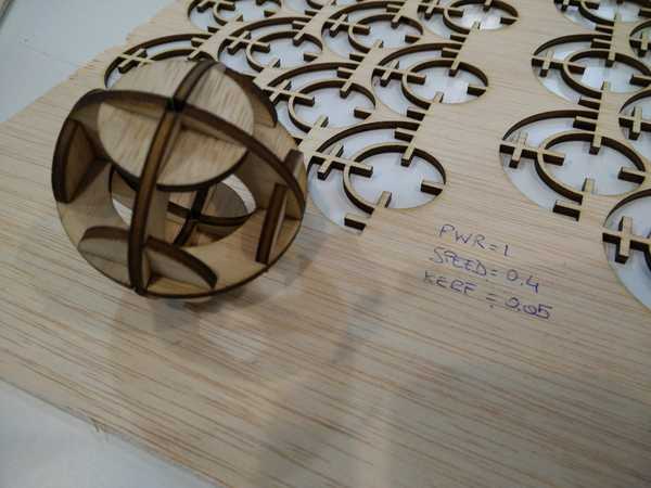
For the laser cutting exercise I took inspiration from this press-fit construction Kit.
The idea is to create instead of the squared piece a rounded version of it. This piece has a radius that fits exactly in the sphere.
I started creating a Solidworks sketch that is fully parametric for the two pieces 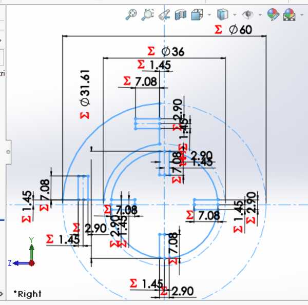
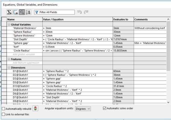
All the dimensions are based on few initial paramaters:
- the sphere radius (eg. 30mm),
- the sphere thickness (eg. 12mm),
- the material thickness (eg. 3mm),
- the cutting Kerf (eg. 0.15mm) every other dimension of the sketch is calculated based on the above.
Download source file (.sldprt)
After setting the parameters I exported the file in .dxf and using Rhino I created multiple copies of the pieces.
The file cleaning is quite consuming so I decided to start using Rhino locally on my machine and have a file ready for cutting.
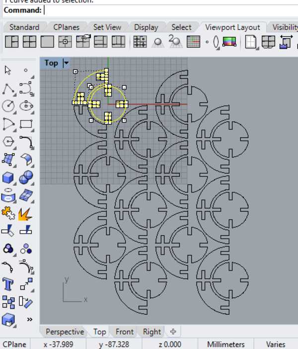
Download source file (.3dm)
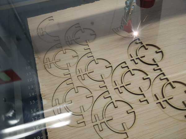
Ready to start at the laser cutter!
This time I used the Trotec Speedy 100 because I found an empty time slot in the schedule :)
I reused the simple test files created to check the laser cut setting and the kerf.
I finally cut the 3mm plywood with the following settings:
| Power | Speed | PPI/Hz |
|---|---|---|
| 100 | 0.4 | 1000 |
The resulting kerf measured is: 0.05mm
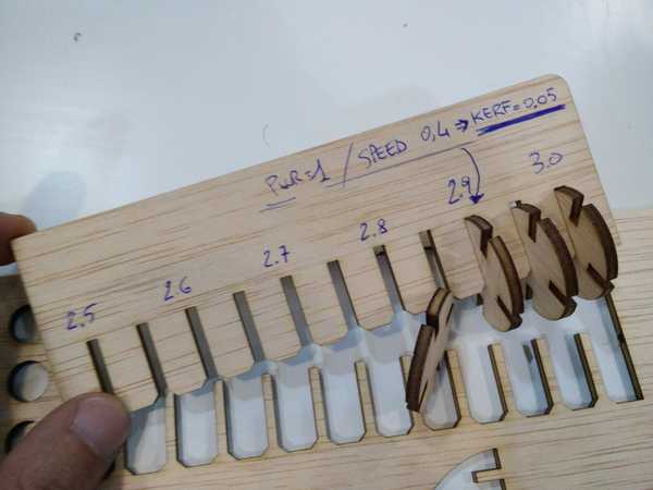
The kerf measure was quite different from the one measured the day before on the other machine so I had to change the parameter and regenerate the Rhino file.
Finally ready for the last print.
And here is the final outcome! :)
Lessons learned
- Avoid using unnecessary common origin point constraints in Solidworks:
I created my 2 pieces in Solidworks using a common center point (the 0,0 origin) only for visual reasons. After parametrizing the entire sketch I found out that a possible solution have a “Circle radius” for the small piece that is bigger than the “Inner radius” of the other piece.
This would cause the two pieces to overlap and make it impossible to cut.
Now it is very difficult to change the origin after many constrainst are based on it (more than 20) - How to create chamfer on round edges in Solidworks?
Using the functionality in Solidworks I managed to create chamfers only wheb on both sides I have a straight line. In my design I wanted to create a chamfer on the circle and didn’t managed to do it. I decided to keep the design simple instead of dividing in many arcs and creating complex structures. - Beware infinite construction lines in .dxf exports
When exporting from Solidworks to dxf I had issues because I was able to see only two perpendicular construction lines in the export. After scratching my head for quite a while I found out that those construction line where considered with infinte length and the export was actually correct… but very very tiny in proportion dimentions to be visible. - Kerf will change a lot!
Based on the laser cutter and the cut settings. While I was regenerating my Rhino file I tried to cut a version with the initial kerf of 0.15 measured from the day before just to give it a try :) …not successfully, parts didn’t fit together at all.
Once I also swapped power and speed by mistake ( 1 and 0.4 ) before cutting. Also in this case the parts where very hardly fitting together! :( Plywood also give much less tolerance than cardboard in case of a wrong kerf.
Laser engraving
The last process I wanted to try is to engrave images and textures on a meterial.
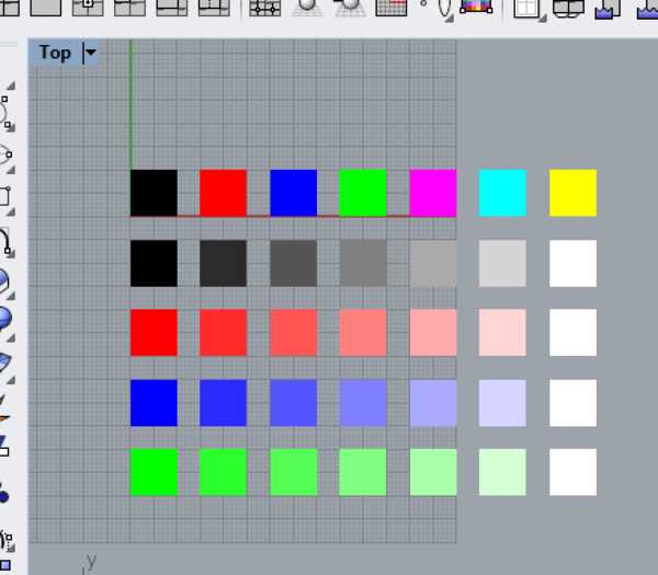
Initially I create a file with many colors and associated those to different setting to be able to try quickly different parameters.
We first learned that the darkening of the surface quickly goes to an upper level then the machine starts going through different layers of wood and the material does not get any darker.
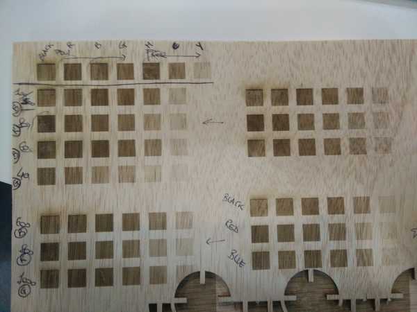
From the first result we got confusing results. For example the line at 800hz (red) frequency is both darker thatn the one at 1000hz (blue) and 600hz (green).
The printing process for “rastering” is translating colors to scales of gray first and then associates that to a certain power/speed/frequency variation. The last three lines on the bottom right, in which we processed different colors with same settings, are proof of this.
The final setting for plywood are:
| Power | Speed | PPI/Hz |
|---|---|---|
| 60 | 100 | 1000 |
Finally I created a grayscale complex image to try different setting on a real case scenario.
Some of the details are lost in the image but here is the final result :) 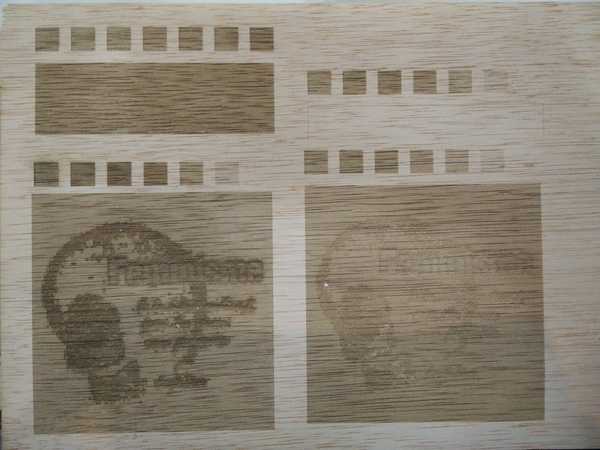
Lessons learned
- Transform your design in a B&W or greyscale format before engraving.
Laser cutting polypropylene
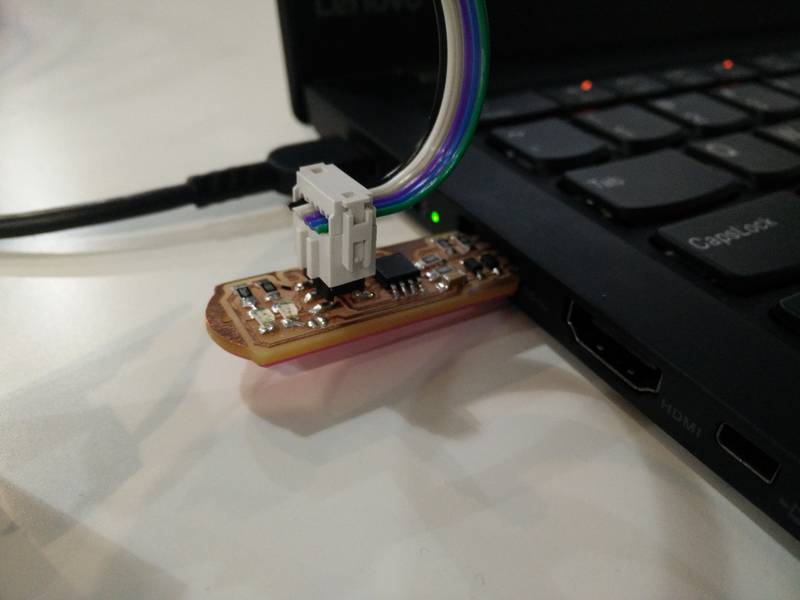
During the week 8 of embedded programming I started to using etensively my USBTiny programmer that I created in week 4 for the electronics production assignment.
The thickess of the programmer USB male connector is same as the PCB board thickness, which is a little bit less than what is necessary in the USB port to keep it stable.
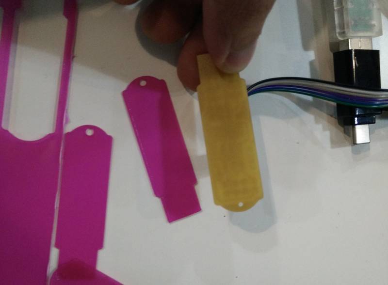
I decided to go back to the laser cutter an make a simple flat shim that could be glued to the bottom of the board. I choosed a non conductive material polypropylene.
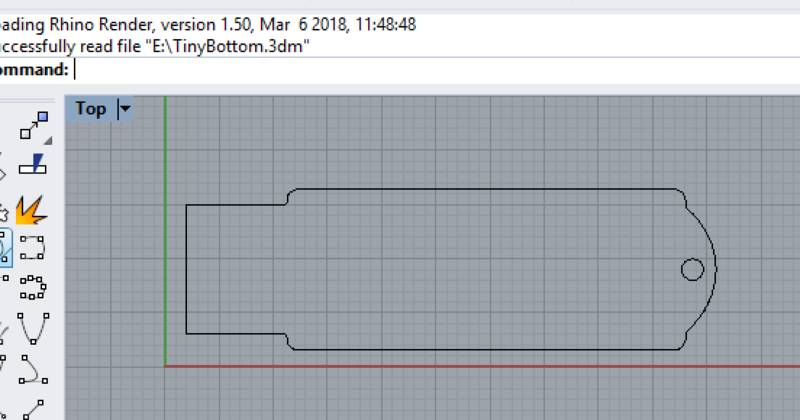
I used the same PCB outline file to convert and generate the file for the laser cutter so that I had already the correct dimensions.
After a bit of trial and error the final parameters for cutting the polypropylene are:
| Power | Speed | PPI/Hz |
|---|---|---|
| 80 | 2 | 1000 |
And here the final result! :)
Download source file (.svg)
Download source file (.3dm)
Lessons learned
- I had a problem with the printer not executing any job. From the Trotec job tool it was marked as a 0:00 seconds job. The file was generated importing a .svg file and lines add thickness/color parameters. The fix was to check the layers and line types in Rhino and set them to defauls to allow lines to be recognised.
Happy Cutting! ![]()