According to the serial input (1 or !1), the LED either blinks or is on when the button is pressed. Code is an amalgamation of the following 3 Arduino example codes:
01.Basics>Blink
02.Digital>Button
SoftwareSerial>SoftwareSerialExample
Making the Connection
The High Low Tech Website was vital for the serial connection. Much of the needed information is there, but saliently:
This Arduino ATTiny IDE ide-1.6.x.zip and instructions for installation is available at the site.
This picture from that website is important for assigning the proper pin numbers in the code.

After installing the Arduino ATTiny IDE. Using the tools menu in Arduino, set:
Board to ATTiny
Processor to ATTiny44
Clock to 20MHz (external)
Port to whatever port your programmer is on (COM29 for me in this case, you may have to try different ones until it works)
Processor to USBTinyISP
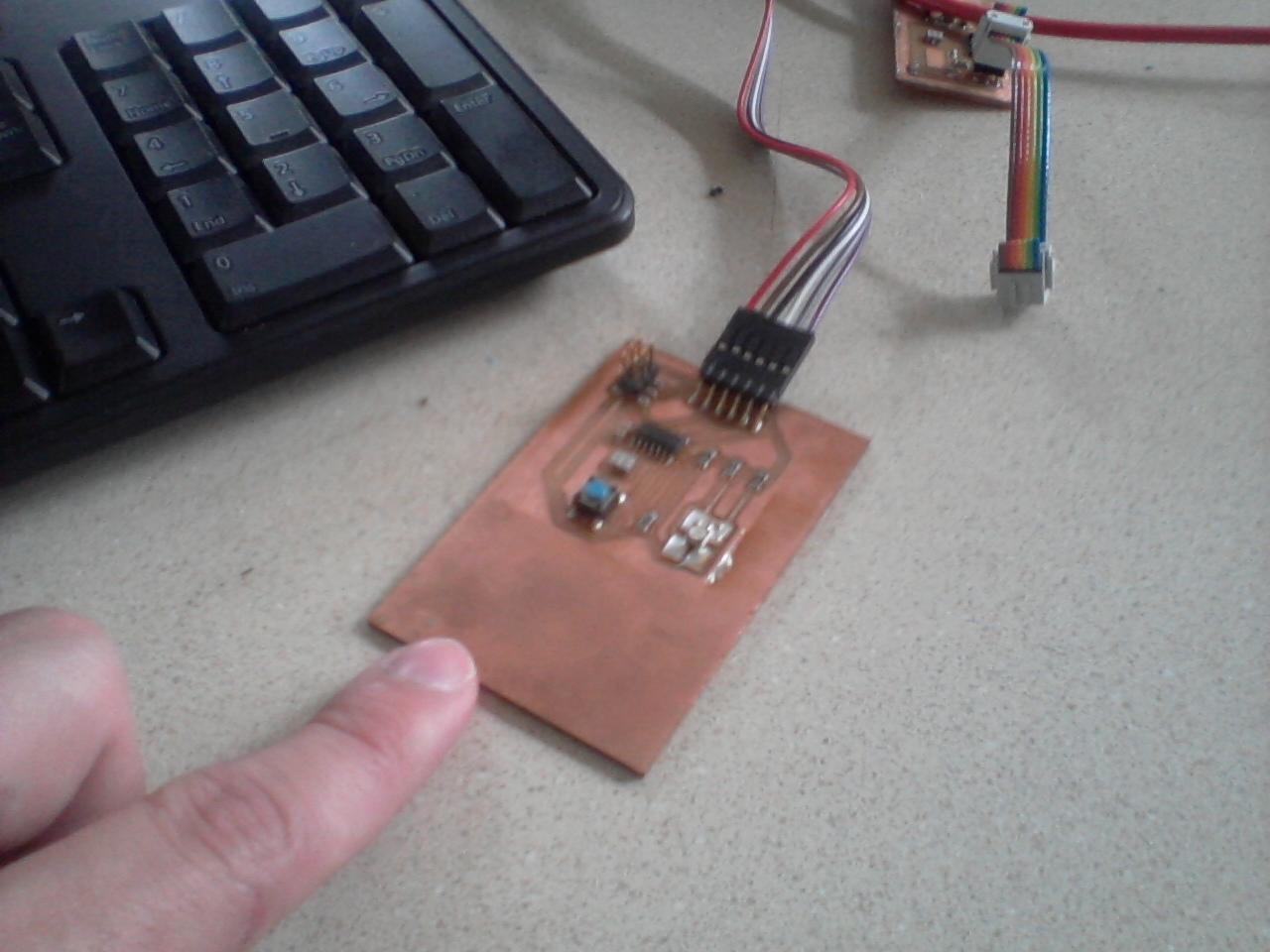
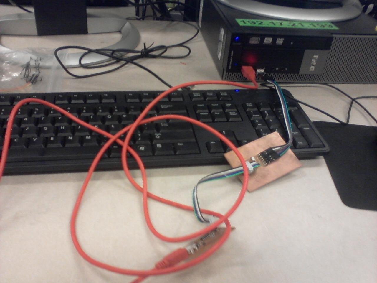
Also, plug in the board. Plug the USB tiny ISP into a USB port using a USB mini cable, and into the board to be programmed by a 6 pin cable. Power also needs to be supplied to the board to be programmed, I plugged into a USB breakout board on the FTDI pins.
Burn the bootloader and upload the code.
In the serial monitor, set the baud rate to 9600. This makes a functional blinking/button light with serial toggle. If you send 1 to the serial port in arduino, it blinks once. If you send something that is not 1, then pressing the button turns the light on.