This week was an expantion of week four's work making a FabISP. A schematic was drawn up and board layout was made in EagleCAD. Inkscape and Photoshop were used to get the file properly rendered for the Roland Modela, which we used to mill the board. Finally the board was populated with pieces similar to week 4.
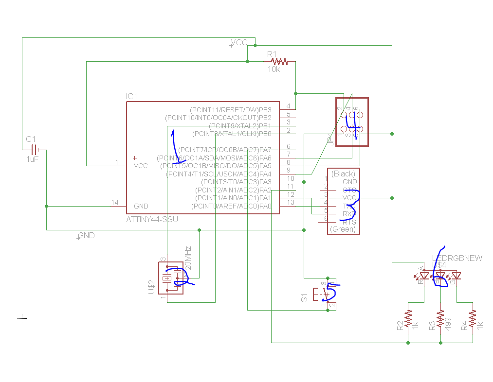
EagleCAD Schematic Designs
The schematic and board> were designed using EagleCAD. The Fab Academy Library had to be added to make the parts available in EagleCad. The ATTiny (1) is in the middle, connected to a 20 MHz resonator (2), a FTDI-SMD-Header(3), a six pin In sequence Circuit Programmer (4), a button (5), and a triple LED light (6).
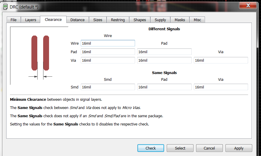
From the schematic, I used the autorouter tool to make a design for the board. In the DRC (1)(Design Rule Check), all the fields in clearance were edited to 16 mil to make the design suitable for the Roland Modela.
Workflow consisted of AutoRouter Tool(2) --> Try for 100% connections --> fail --> ripup;(3) all the connections --> move components around --> AutoRouter Tool.

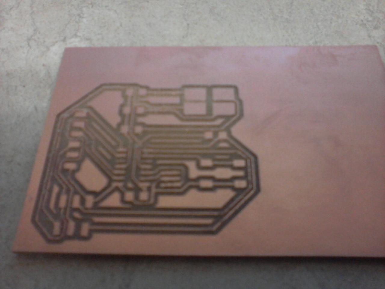
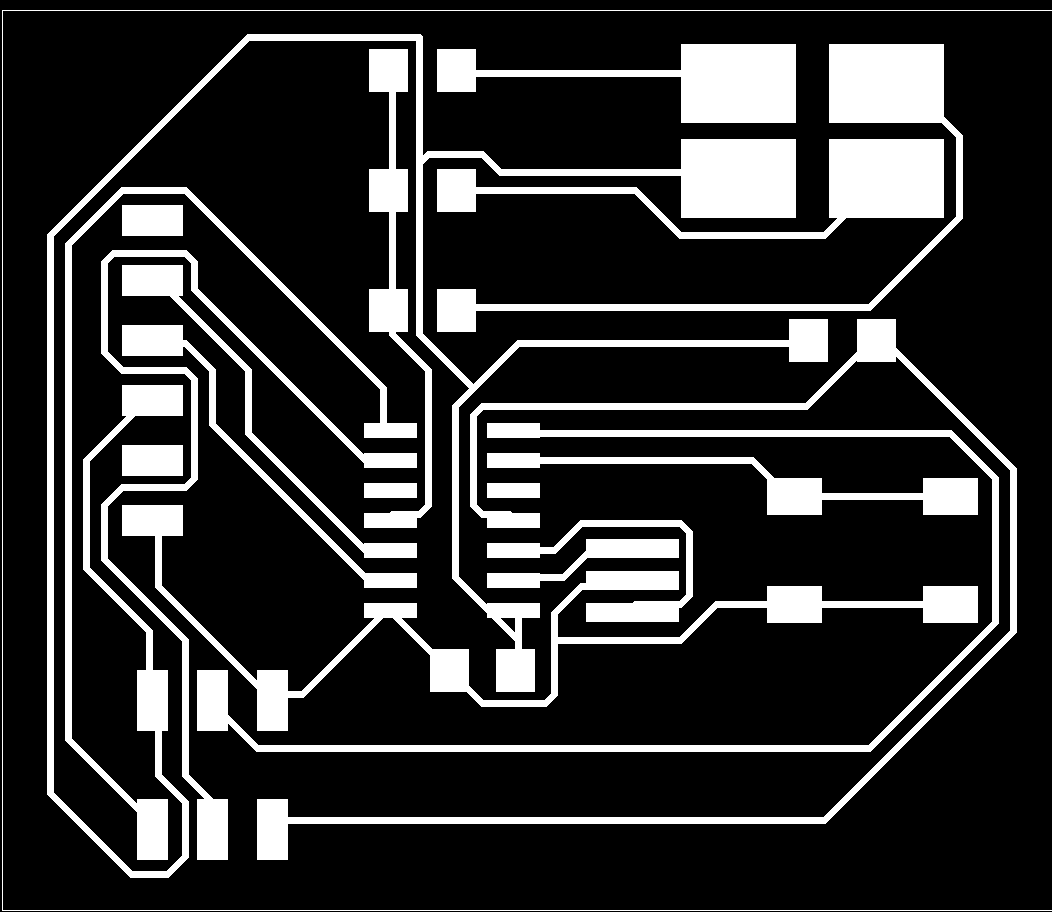
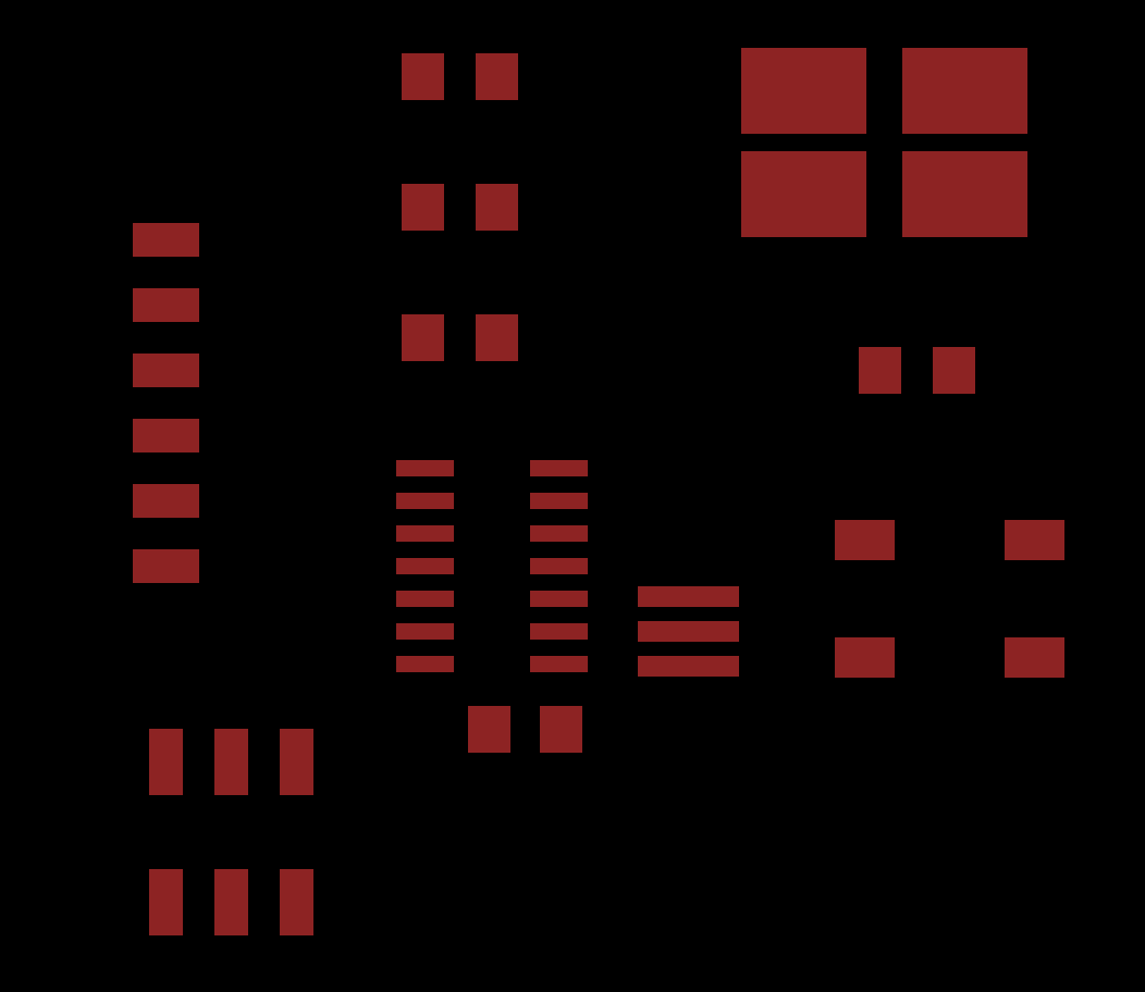
The board then needed to be exported, using EagleCADs export image tool. Layers were set so that only layers 1 and 20 were showing, then the image was exported as a 600 dpi PNG. We loaded that PNG file into Photoshop to get the proper dimensions, as it was not sized properly for our roland program. The image was then rescaled using inkscape to the dimensions photoshop gave us, and then exported as a new 600 dpi PNG from inkscape.

Next, we were ready to mill, solder, and populate. This process is functionally the same as week 4 FabISP milling.