File here
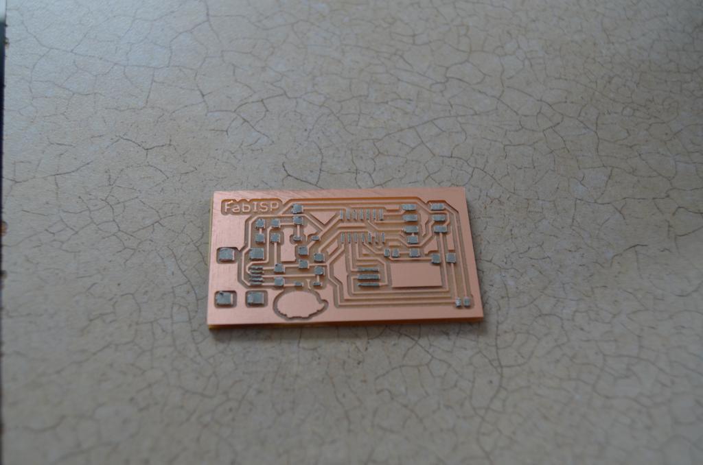
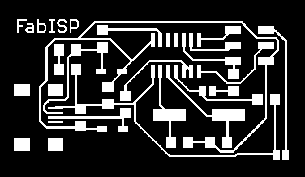
We used the Roland Modela to mill the FabISP using a fab module called make_png_rml. Instructions for instillation and running are here.
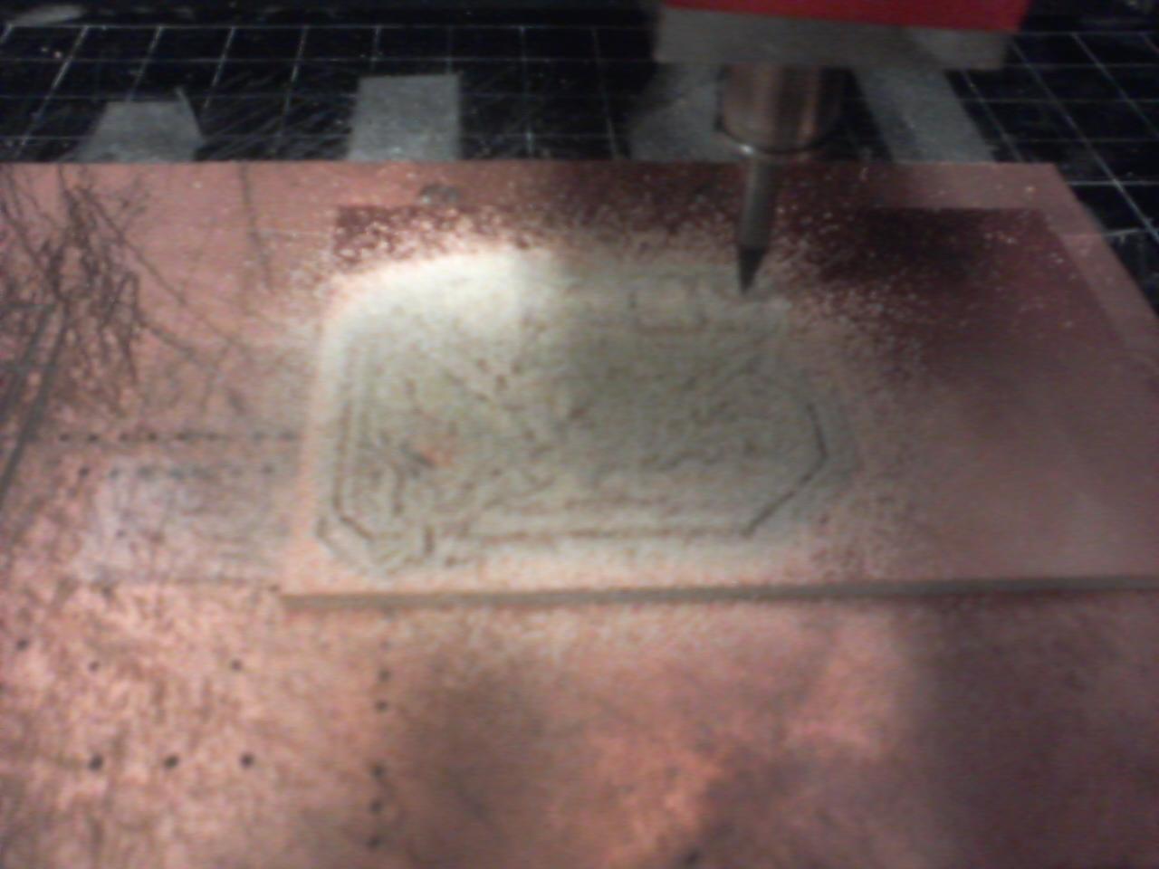
Setting up the Modela Double sided tape is used to attach a sacrificial layer of a blank PCB to the bed of the Modela. Double sided tape is then used to attach a board to mill onto the sacrificial PCB. Take care to avoid air bubbles in the tape, as you wan the surface to be as flat and smooth as possible.
A 1/64" drill bit is used for milling traces. This drill bit is tiny and fragile. Handle with care. Only use one set screw in setting up the bit. Workflow consists of:
1) Unscrewing the set screw on the drill of the modela and putting a 1/64" inch bit in deep, reattaching the set screw.
2) Pressing the view button the the modela, moving the drill and bed into place.
3) Aligning the drill bit above the lower left corner of your board to be drilled using the fab module settings (more about this below.)
4) Pressing down on the Modela, lowering the bit close to the PCB.
5) Unscrewing the set screw, being careful to not let the bit drop onto the board. Instead, hold the bit and let it set onto the top of the board gently.
6) Rescrew the set screw with the bit touching the board.
The module has various settings.
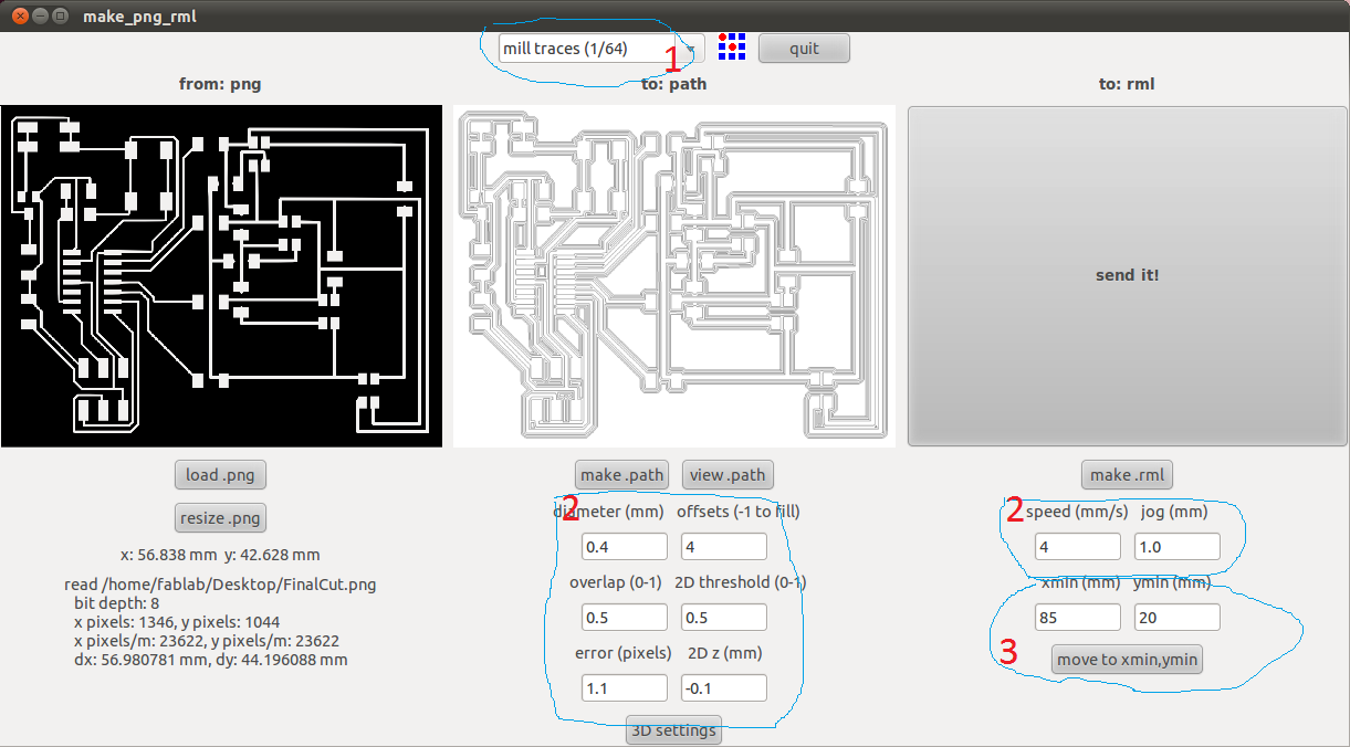
1 is the size of the bit. A 1/64 inch bit is used to make the traces.
2 All of the settings at 2 are automaticly changed after you set the bit at 1. I never messed with them.
3 is used to line up your the lower left corner of the png file you are milling to the lower left corner of the place where you want the board to be drilled on the Roland. These numbers need to be manually set each time you mill a board.
