Words cannot express the amount of stress and frustration this assignment has caused.
Files
Schematic
Board
Fab Library
Png for Modela
Stencil for Solder
Master Code
Slave Code
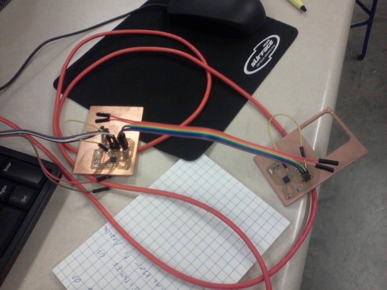
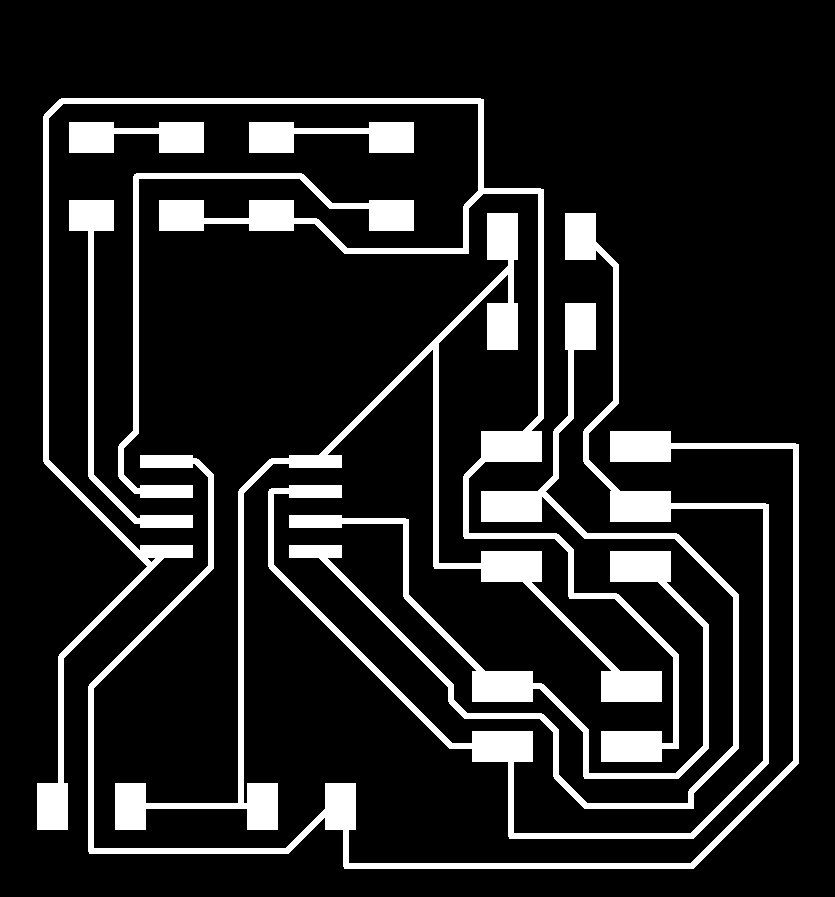
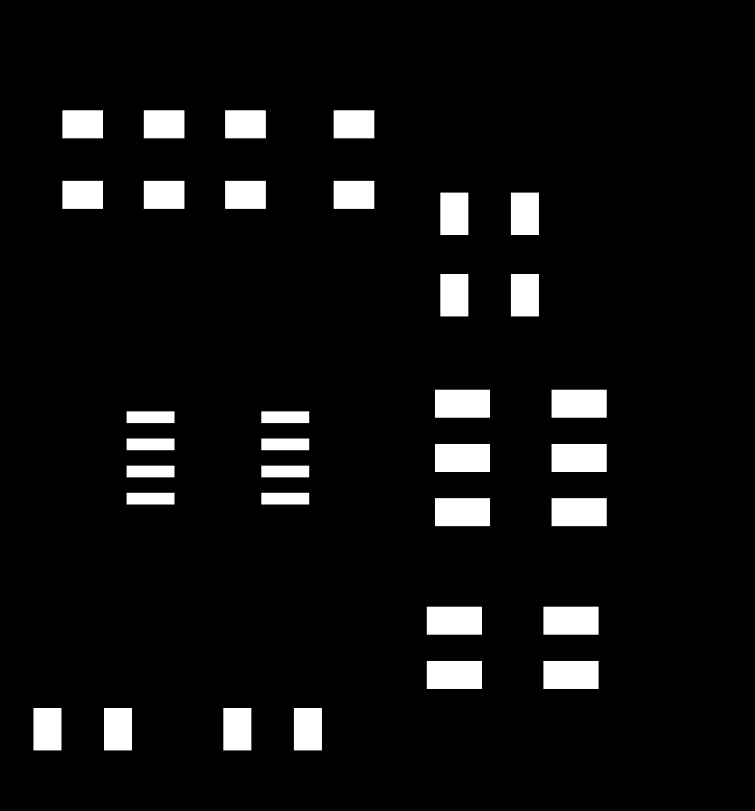
Circuit Board Design
The Schematic and Board were designed in EagleCad using the Fab Library. It was then milled using a Roland Modela. A stencil was made to apply soldering paste to the contacts and then a toaster oven was used to solder components the components to the board. See weeks 4, 5 and 6 for more details on these techniques.
Notes, I made boards and more boards trying to get this to work to no avail. I troubleshot and troubleshot to the best of my ability. I enlisted more the help of my electrical engineer compatriot Jeff Putney. I messed with code. I was fighting a losing battle. 

Programming the Board
The TinyWire libraries TinyWireS and TinyWireM need to be downloaded from this webpage and properly installed into arduino. Directions to install Arduino libraries here. These files also have examples which would ultimately become our code.
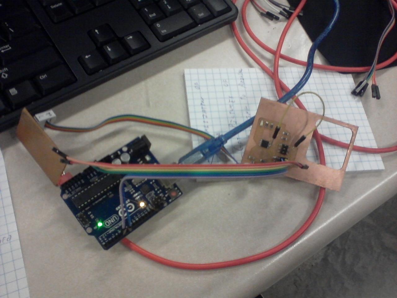
Dispite my best efforts, I could get Arduinos to talk to the boards, but I could not get them to talk to each other.
Troubleshooting Process
The troubleshooting process was refined over the course of the project. It really begins when the bootloader fails to load.
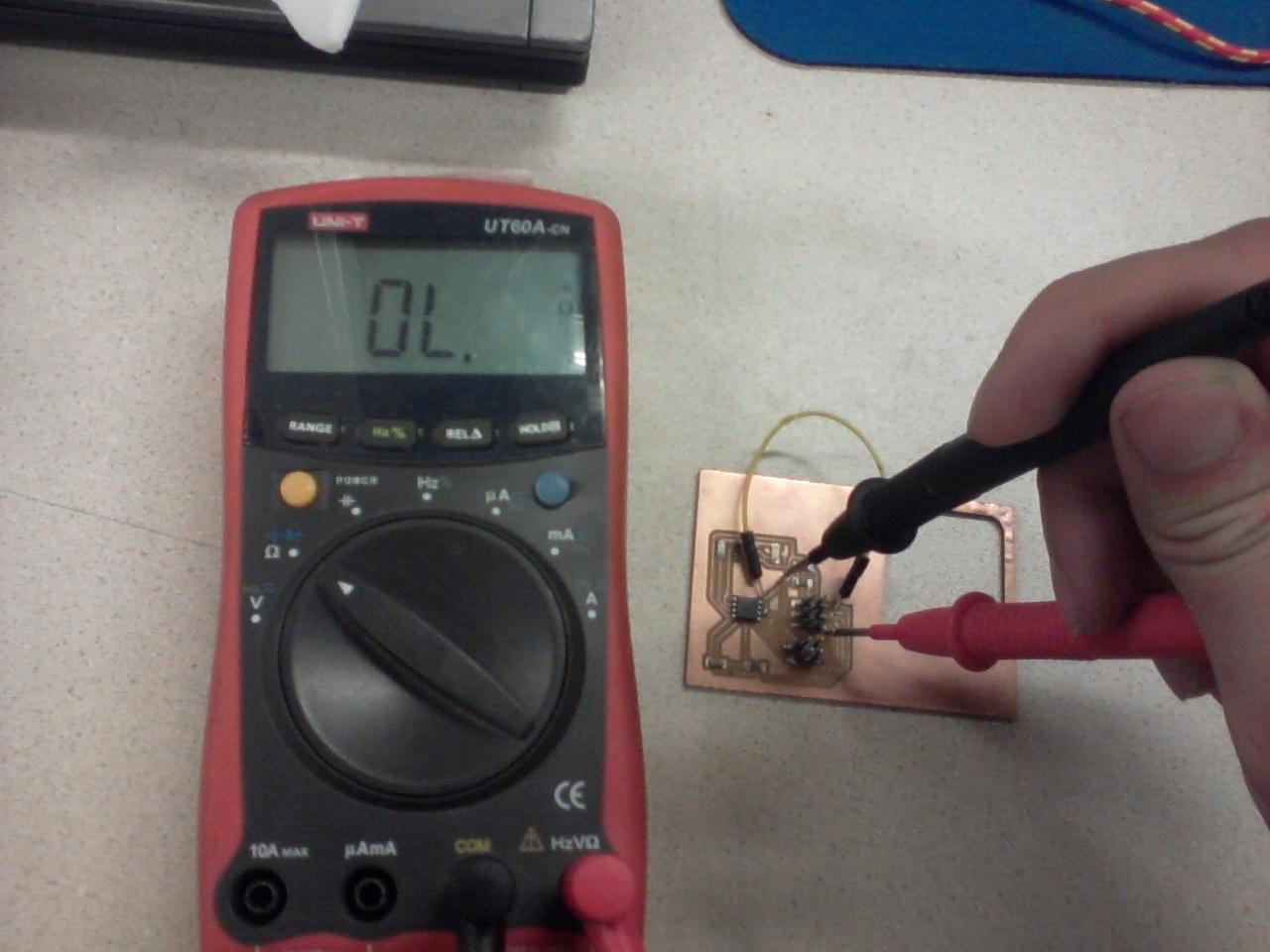
This tells me I have a problem in my traces or components being attached, or, failing that, there is a major problem in the board designed. A multimeter is used to see if components are properly connected to pins, as well, as to check if different pins are improperly connected to eachother or ground.
Note, if you manually solder 4 and 6 pin headers onto the board, sometimes the pins soften the plastic piece that holds the pins in place. This makes soldering harder.
My first boards only had one light. A second set of boards were made with two lights. Using the two lights, I had the slave blink it powers on in the setup, and then when it receives data in the loop. On the Master, I had the different lights blink at each step of the data sending process.

I was able to isolate the problem to the point where I the master would send data but an ATTiny45 slave would never receive it. However, I could get the master to send data to an Arduino and the Arduino would.