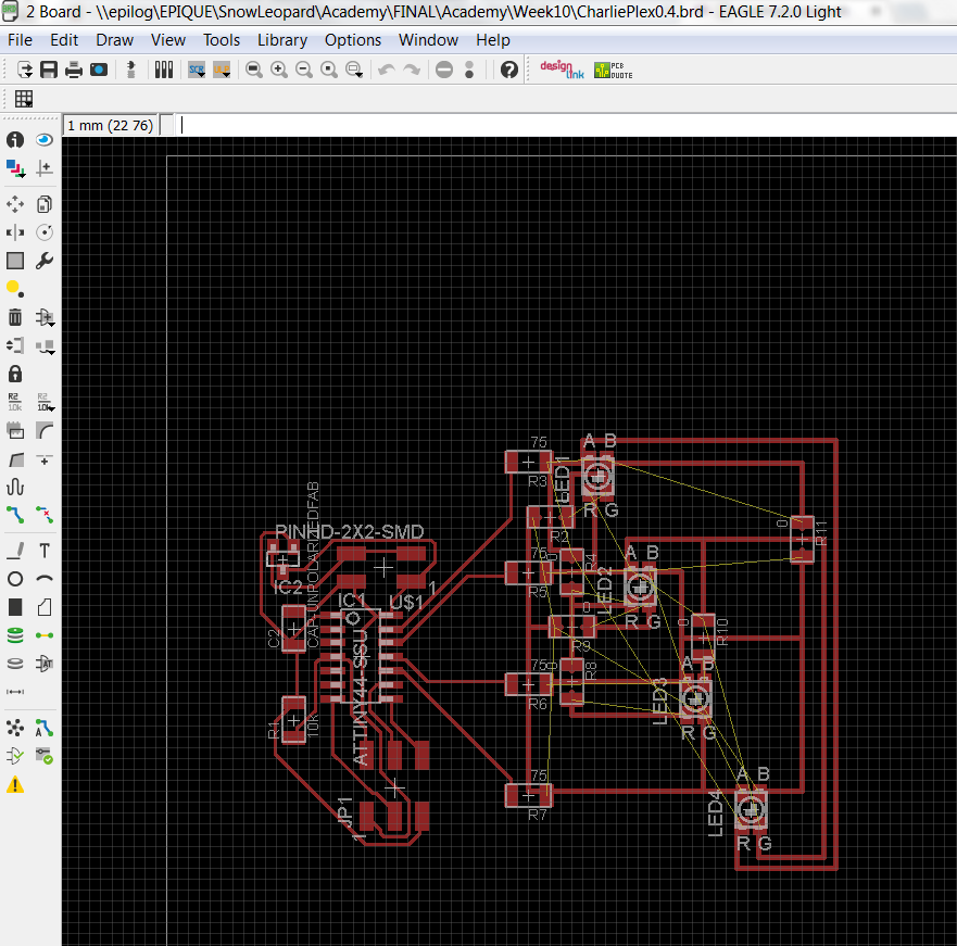
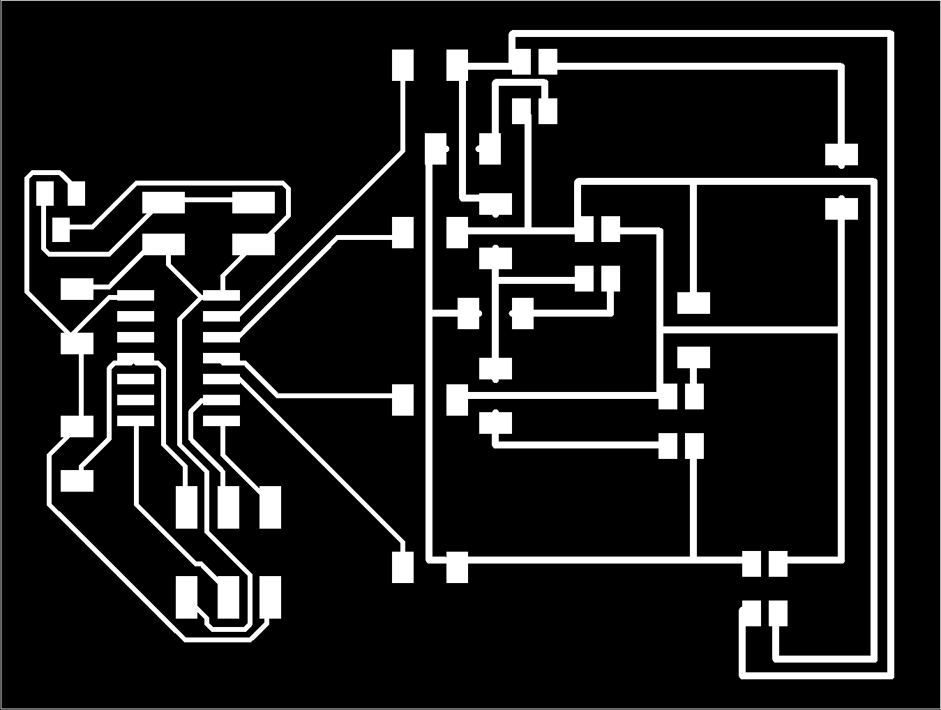
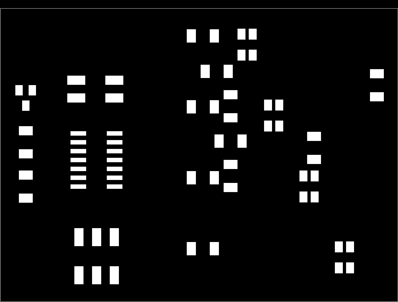
Circuit Board Design
The schematic and board were designed in EagleCad using the Fab Library. It was then milled using a Roland Modela. A stencil was made to apply soldering paste to the contacts and then a toaster oven was used to solder components the components to the board. See weeks 4, 5 and 6 for more details on these techniques.
Notes, I manually designed the wiring on for LEDs. There isn't really a grand method/organization to it, I drew traces close to what my schematic looks like as best I could and then just used 0 ohm resistors to hop over wires as needed.
Programming the Board
The board was programmed with Arduino. Code is here. There is decently explicit pseudocode in the introduction explaining what is going on, also available at the end of this page. I wanted to control all the red lights, green lights, and blue lights as groups, and the code reflects that rather than more general individual light control. It works well for understanding and visualizing how Charlieplexing works and ties in with the RGB LEDs well. If I was a more proficient programmer I would have written more general, all purpose code and then applied it, but this is sufficient and quite informative on what is going on while Charlieplexing.
Final Board
The final board initially lights all the reds, then blues, then greens for a second each. Then the board cycles through the individual lights one at a time.
Hat Tip to Jeff Putney for awesome video editing/musical selection.