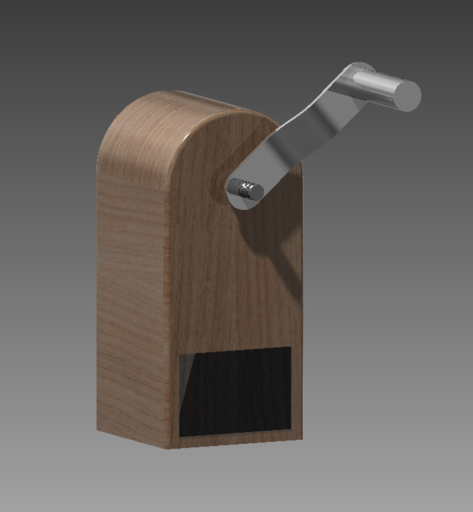
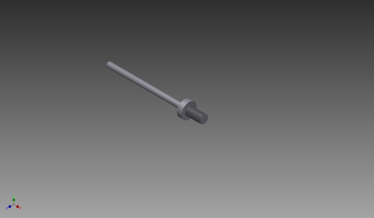
Week 02. Computer-aided design

For this week's assignment I modeled the possible final project from the assignment in week 1. This project proposal is an interactive energy generator. If you rotate the handle, the generator gives you feedback on how many energy you generated and what you can do with it. Using different computer-aided design (CAD) programs I modeled three parts of this generator:

  • the generator housing
  • a handlebar
  • a feedback display

Assignment

model (draw, render, animate, simulate, ...) a possible final project, and post it on your class page
final sketch


Handlebar

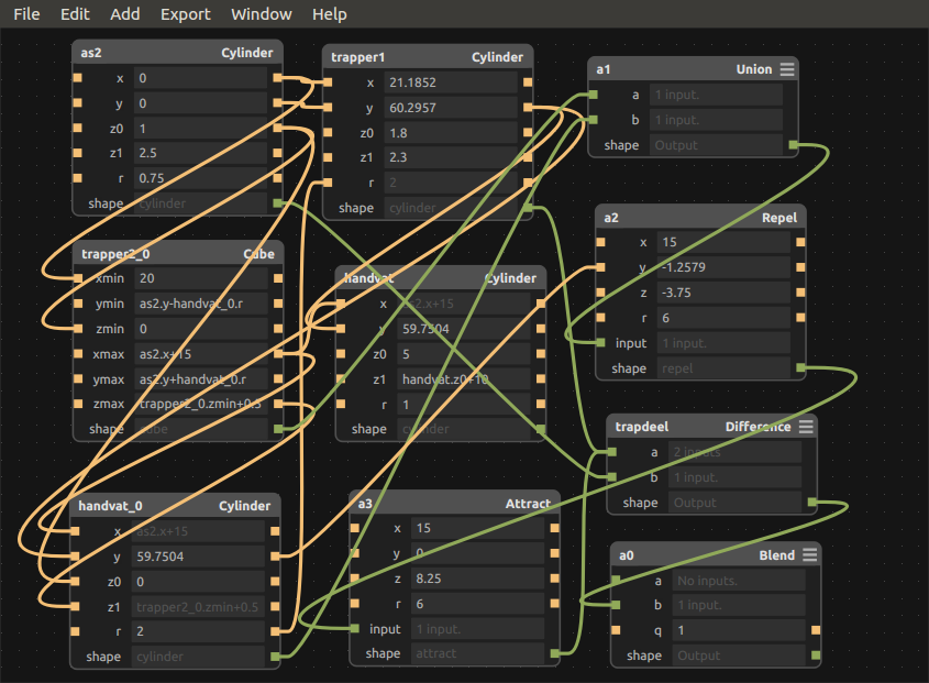
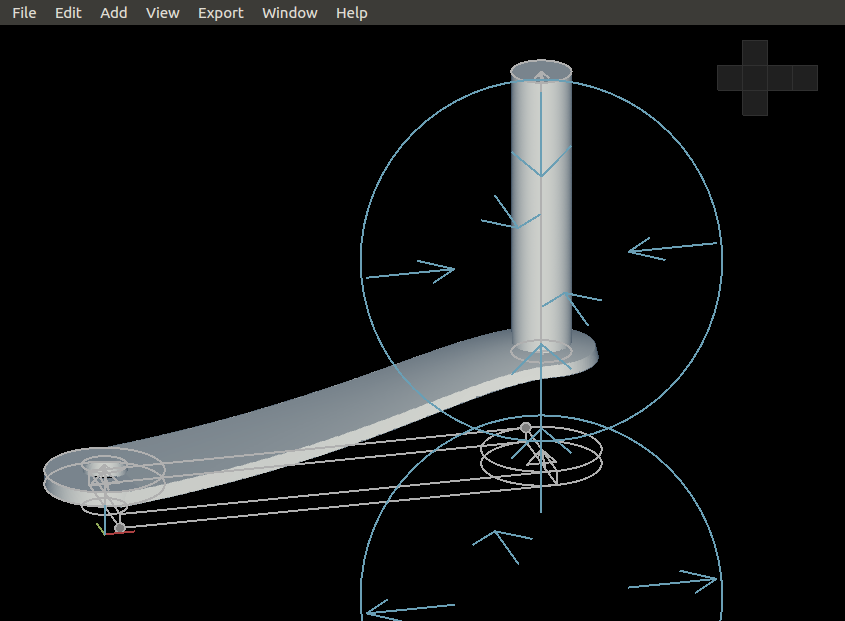
To generate energy with the interactive energy generator you have to spin the handlebar. The handlebar will be connected to a generator. To model this I used Antimony, an experimental CAD tool. I just started experimenting in Antimony and I tried out the different features of the program. In Antimony shapes are defined by mathematical expressions and you can make relations between those shapes: adding, subtracted etc. Below you can see a screen shot of the graph window of Antimony, in which you see the values I used for the mathematical expressions. In the viewer window you see can the shapes.

screen shot of the Antimony graph window
screen shot of the Antimony view window
The blue spheres you see show the functions 'repel' and 'attract' I used for the curve in the handle bar.

handlebar antimoni file handlebar stl file
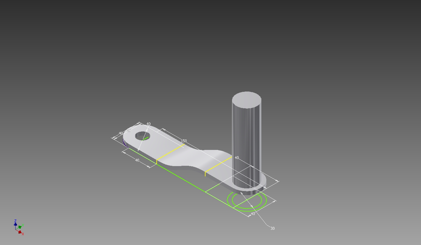
3D model

In the end I worked this model for the handlebar and exported it as an .stl file to use further on. You can click and turn the model to see different sides. It seems you are using an outdated browser that does not support canvas.

Housing

The housing of the generator is designed in three phases: first an outline, than a three-dimensional shape of the outline and finally some adjustments. For each phase I used a different CAD program: LibreCAD for the outline, FreeCAD to turn it 3D and Inventor for the adjustments. I could have done it all in Inventor, but wanted to try different types of CAD software.

Outline

I started the design the housing in LibreCAD. With LibreCAD I made an outline of the housing:

dxf file

3D shape

I turned the outline into a three dimensional shape using FreeCAD. You can click and turn the three dimensional shape:


stl file It seems you are using an outdated browser that does not support canvas.

Inventor

First of all I imported the shape from the housing from FreeCAD and made some adjustments: made the shape hollow, made holes for the shaft and wiring, and smoothed the edge.

Display in Inkscape


For the feedback display I designed this image with Inkscape:

Assembly

To assemble all parts I used Inventor. I couldn't import the image I wanted to use for the display, so the display is blank. Finally I assembled the parts. I assigned different materials to the different parts, aluminum for the handlebar, steel for the shaft and wood for the housing.

Handlebar

I couldn't import the .stl shape file of the handlebar into Inventor, so I had to redraw it in Inventor.

Shaft

In Inventor I designed a shaft to attach the handlebar to the generator:

Final Result