Week XIII
Lesson April 29th 2015
Review May 6th 2015
Assignment
design and build a wired &/or wireless network connecting at least two processors
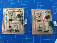
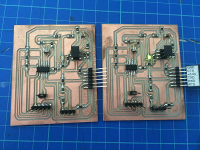
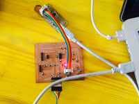
For the assignment of this week, I decided to prepare two asynchronous serial modules to make them communicate with each other with simple message exchanges.
The exercise includes a first part where you have to draw cards from examples provided by Neil.
I chose this card, the same card will be programmed first in serial and then with modules bloutut as any I've seen in the example of a student of the past: Dan Chan.
In recent assignment I found many teachings on the website of Dan Chan, and a lot of inspiration for my work.
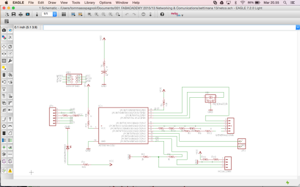
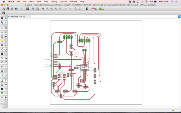
The first thing I did was to copy the components from the board of Neil and I eagle searches for libraries, then I added a red LED, and two resistors to hold the 3.5 volt module bluetooth 2kOhm R2, R4 1kOhm. During this assignment I found a good solution to the bridges, which means the use of resistance 0, this resistance just put it in the circuit and well placed I can help in routing the board.
Mynetboard:
- R1 10k / Res 10.0k ohm 1206 SMD
- R2 2k / Res 2.0k ohm 1206 SMD
- R3 499k / Res 499k Ohm 1206 SMD
- R4 1k / RRes 10.0k ohm Ohm 1206 SMD
- R6 0k / RRes 0.0k ohm Ohm 1206 SMD
- R9 0k / RRes 0.0k ohm Ohm 1206 SMD
- R10 0k / RRes 0.0k ohm Ohm 1206 SMD
- R11 0k / RRes 0.0k ohm Ohm 1206 SMD
- R12 0k / RRes 0.0k ohm Ohm 1206 SMD
- R13 0k / RRes 0.0k ohm Ohm 1206 SMD
- R14 0k / RRes 0.0k ohm Ohm 1206 SMD
- R15 0k / RRes 0.0k ohm Ohm 1206 SMD
- R16 0k / RRes 0.0k ohm Ohm 1206 SMD
- R17 0k / RRes 0.0k ohm Ohm 1206 SMD
- R18 0k / RRes 0.0k ohm Ohm 1206 SMD
- C1 1uf / CAP CER 1UF 1206
- IC1 t44 / ATTINY44A - ssu
- J1 ISP /
- J2 FTDI / 2x2 connectors
- J2 FTDI / 6 connectors
- LED red 1206 SMD
- Switch Tactile
"Bluetooth communication":
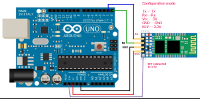
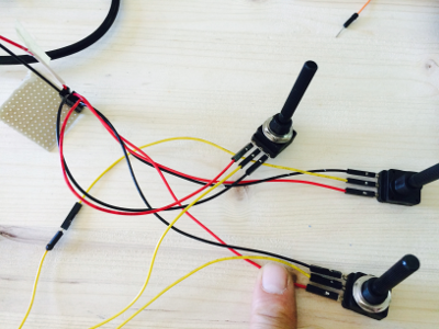
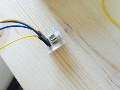
My objective was to create a wireless communication between two microcontroller with two HC-05 bluetooth transceiver. In order to obtain an automatic connection I used a little program able to sent AT commands via Arduino serial monitor ( il file HC-05), to set one bluetooth module as Master and the other as Slave. In this manner I wanted to use the Master board to send data, picked from three 10k Ohm potentiometers (file MASTERCONTROL), to the Slave and this should have changed the light intensity of the three colour of an RGB LED (file LEDCONTROL)."
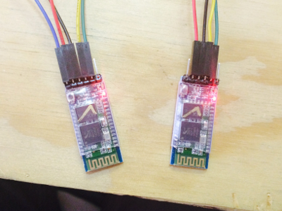
Modulo Bluetooth Transceiver Master/Slave
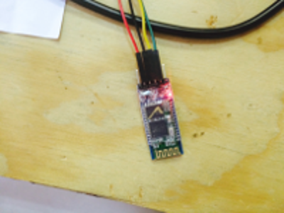
This Module Bluetooth SPP / Serial Port Protocol) allows you to create a wireless serial connection with a range up to 10m . It uses an integrated unit HC- 05 welded on a base containing also a service circuit and a header male 6 - pin , 2.5mm pitch , for connection either in slave mode ( defoult ) that in Master mode .
Specifiche HC-05
- Protocol : Bluetootj v.2.0 + (Enhanced Data Rate )
- Frequency : 2.4GHz ISM band
- Modulation: GFSK ( Gaussian Frequency Shft Keying)
- Current: 30 / 40mA during paring , 8mA after
Objective: To connect two modules bluetooth HC-05 automatically
-you will use AT commands to the HC05 modules.
What is needed:
- 1 Rotomolduina;
- 2 Modules HC-05;
- Rubber thread;
- IDE Arduino.
Arduino code:
/ * Program to send AT commands via serial monitor * / #include SoftwareSerial BtSerial (10, 11); // RX | TXvoid setup () {pinMode (9, OUTPUT); // This will pull the pin HC-05 pin 34 (pin key) HIGH to switch to AT mode digitalWrite module (9, HIGH); Serial.begin (9600); Serial.println ("Enter AT commands:"); BTSerial.begin (38400); // HC-05 default speed in AT command more} void loop () {// Keep reading from HC-05 and send to Arduino Serial Monitor if (BTSerial.available ()) Serial.write (BTSerial.read ()); // Keep reading from Arduino Serial Monitor and send to HC-05 if (Serial.available ()) BTSerial.write (Serial.read ()); } Use either module HC-05 for configuration:
Slave configuration
-Connect the form without tension;
-open the serial monitor;
-When appears "Enter AT commands", connect the power to the module;
-in monitor serial write AT and hit enter;
-The module will respond "OK";
-in monitor serial write: AT + ROLE = 0 and press enter; (We selected the slave)
-to ensure that the command has been received write AT + ROLE?
-in monitor serial write: AT + = BIND and hit enter;
-to see if the BIND is BIND did write AT + ?, in the serial should read + BIND: 0: 0: 0
-in monitor serial write AT + ADDRESS? Mark the number that will appear, that the MAC in our secure;
-disconnettere tension from the bluetooth module and then remove it;
Configuration Master
-Connect the second module HC-05;
-take in the same manner as the previous configuration but with the following commands;
-write: AT + ROLE = 1; (We set the condition Master)
-sincerarsi the control must be implemented with AT + ROLE?
-write: AT + BIND = MAC address of the Slave and press enter;
-Make sure the command has been implemented by writing AT + BIND?
-disconnettere tension bluetooth module and remove it.
Now we have a master module and a slave that communicate with each other as soon as you light up.
Dowload file board
Dowload file programming