Week 3: Computer-controlled cutting
Assignment
Design, make, and document a press-fit construction kit that can be used for more than one purpose.
Fab Academy Course details | Video of lecture
Approach
I decided to bend the rules of the assignment slightly, using the output of the assignment to have a dual purpose. This allowed me to focus on a personal area of interest - furniture.
Workflow
Paper Sketches > Blender > Adobe Illustrator > Corel Draw > Trotec Laser
I decided to explore the creation of dual purpose chair and table design - one which provided a spacious table area with integrated chairs as part of the overall asthetic
Blender was used very early in the design process to basically sketch a very simple design lacking detail, merely as a means to add color and depth to the concept. The parts of the chair and table were created from a single primitive, scaling along all three axis and color added during a single Cycles render.
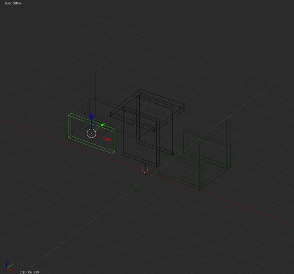
Initial sketches with wireframe view
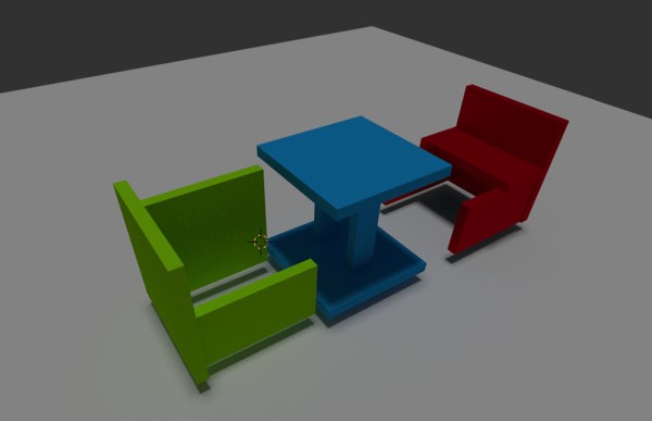
Initial sketches with a material render
Illustrator was used to create the outline paths for each part, ensuring the appropriate lattice was designed for 3mm of material. One of the limitations of using Illustrator is that you are constrained to a material thickness in the design process and I would have preferred to have used an application such as Antimony to develop the design - an opportunity I intend to resolve over the coming weeks.
Two sets of files were created for the design.
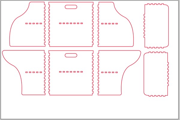
Chair design
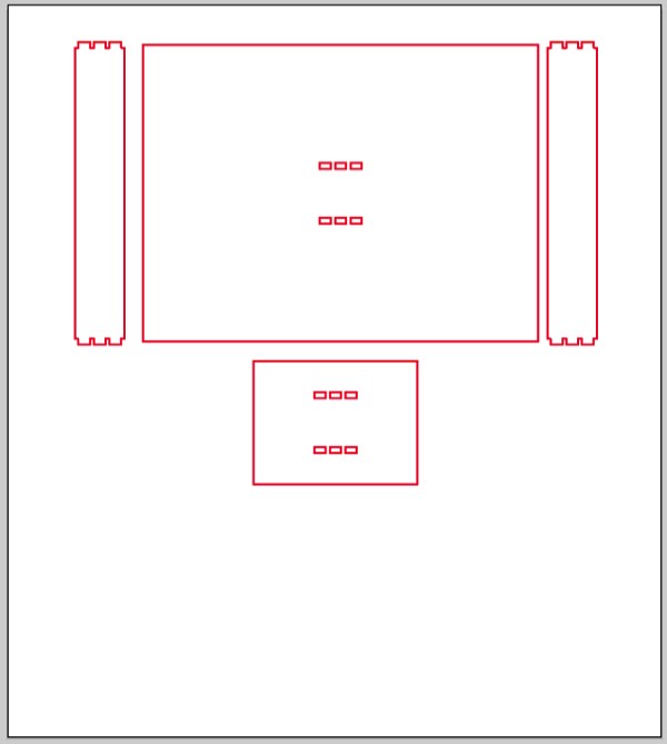
Table design
Each fileset was sent via Corel Draw into a Trotec Speedy 300 laser cutter on a custom corrugated cardboard setting. The cutting of the templates had to be re-done twice, as the tolerance between the lattice was too low.
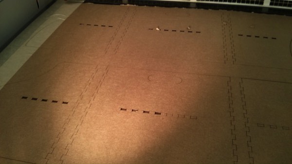
Cardboard very rarely lies completely flat, using masking tape to secure is very handy.
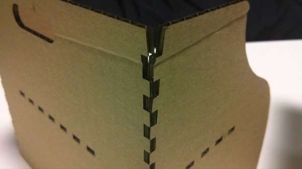
Not all the joints worked well - bent cardboard created a challenge on the corners.
The result was a unit 200mm x 150mm x 150mm when fully closed. Ideally end design for a scale version of this would suit a heavy 25mm plywood material, creating a robust and solid framework. An observation during the final process of piecing together the press fit design, is that the table base may have to be fabricated with a heavy weight and/or greater surface area for stabilisation.
Completed Designs
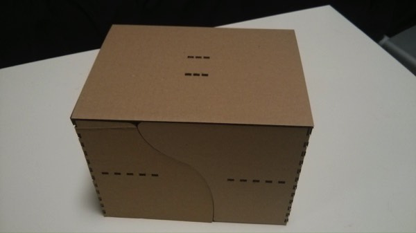
Closed
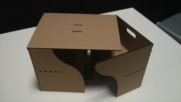
Partially open
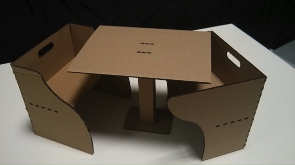
Partially open
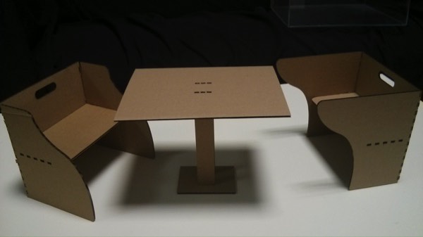
Fully open
Next Steps
Take the illustrator designs into Antimony and FreeCAD to develop a parametric design ready for CNC Milling with plywood. Develop a scale model of the design.
