The time had come! The brain of the project will be growing from now on, no excuses left!
Combining all the possible instructions of the microcontroller to achieve the desired behaviour can be tough. That's why the goal of this week is to learn the basics about microcontroller programming.
In order to do that, I read the full datasheet of the ATmega168A. There I learned about the architecture and its possibilities. Obviously I didn't memorize everything because I know I can take a look at that document in case I need any of the described features.
I had worked with PIC microcontrollers previously, but reading about all its features didn't come as a surprise.
To start a program from scratch is always a tough job, but if you are not 100% sure that the hardware that is going to support that program is working as expected, the process can become frustrating. Where's the error? Is it on the board? Could it be in the software?, or... just everywhere?!
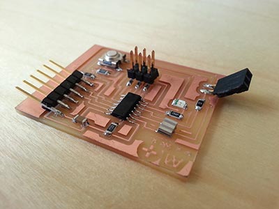
That's why I decided to start programming the board using the echo example, as Neil suggested. Everything behaved as expected. In a few minutes the board was answering to the keystrokes through the serial port.
Loading the program was as easy as executing the makefile with the "program-usbtiny" parameter and waiting until it was loaded in the microcontroller.
To take it one step further, I analyzed the code of the serial example with interruptions. Once I understood the configuration section and how everything worked, I started playing around with the instructions.
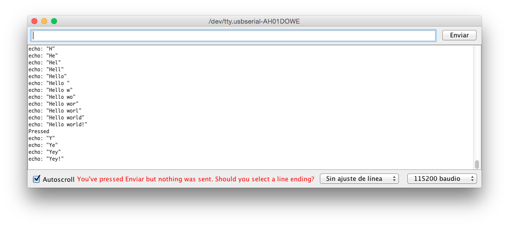
Now, each time a keystroke is sent to the microcontroller through the serial port, it sends the whole buffer and the led blinks. If the board button is pressed, the led blinks, a "Pressed" word is sent through the serial port, and the buffer is erased. From then on, the user can send a new sentence to the microcontroller without overlapping it with the one before.
Initially everything seemed to work fine, but after a few keystrokes I realized that some strange characters were being sent and received through the serial port. After some research I got to the conclusion that my program was not being correctly synchronized with the serial port of my computer. Changing and reordering some instructions solved the problem, or at least that's what I thought.
That solution (without having to change the model of the microcontroller or the pins of the components) made me realize that the synchronization issue was not a trivial problem to solve; if I changed the instruction order, the serial port may read/write incorrect values.
Anyhow I didn't like the solution. It should work regardless of the instruction order.
Finally, I got to the conclusion that the serial buffer was not empty. I changed the code to send an empty char (0) before sending the whole array. That worked perfectly, the program works even changing the order of some of the commands.
- //
- //
- // hello.ftdi.44.echo.c
- //
- // 115200 baud FTDI character echo, with flash string
- //
- // set lfuse to 0x7E for 20 MHz xtal
- //
- // Neil Gershenfeld
- // 12/8/10
- //
- // (c) Massachusetts Institute of Technology 2010
- // Permission granted for experimental and personal use;
- // license for commercial sale available from MIT.
- //
- // Modified by Alejandro Escario
- // Mar 2015
- #include <avr/io.h>
- #include <util/delay.h>
- #include <avr/interrupt.h>
- #include <avr/pgmspace.h>
- #define output(directions,pin) (directions |= pin) // set port direction for output
- #define set(port,pin) (port |= pin) // set port pin
- #define clear(port,pin) (port &= (~pin)) // clear port pin
- #define pin_test(pins,pin) (pins & pin) // test for port pin
- #define bit_test(byte,bit) (byte & (1 << bit)) // test for bit set
- #define bit_delay_time 8.5 // bit delay for 115200 with overhead
- #define bit_delay() _delay_us(bit_delay_time) // RS232 bit delay
- #define half_bit_delay() _delay_us(bit_delay_time/2) // RS232 half bit delay
- #define char_delay() _delay_ms(10) // char delay
- #define serial_port PORTA
- #define serial_direction DDRA
- #define serial_pins PINA
- #define serial_pin_in (1 << PA0)
- #define serial_pin_out (1 << PA1)
- #define max_buffer 25
- void get_char(volatile unsigned char *pins, unsigned char pin, char *rxbyte) {
- //
- // read character into rxbyte on pins pin
- // assumes line driver (inverts bits)
- //
- *rxbyte = 0;
- //
- // delay to middle of first data bit
- //
- bit_delay();
- //
- // unrolled loop to read data bits
- //
- if pin_test(*pins,pin)
- *rxbyte |= (1 << 0);
- else
- *rxbyte |= (0 << 0);
- bit_delay();
- if pin_test(*pins,pin)
- *rxbyte |= (1 << 1);
- else
- *rxbyte |= (0 << 1);
- bit_delay();
- if pin_test(*pins,pin)
- *rxbyte |= (1 << 2);
- else
- *rxbyte |= (0 << 2);
- bit_delay();
- if pin_test(*pins,pin)
- *rxbyte |= (1 << 3);
- else
- *rxbyte |= (0 << 3);
- bit_delay();
- if pin_test(*pins,pin)
- *rxbyte |= (1 << 4);
- else
- *rxbyte |= (0 << 4);
- bit_delay();
- if pin_test(*pins,pin)
- *rxbyte |= (1 << 5);
- else
- *rxbyte |= (0 << 5);
- bit_delay();
- if pin_test(*pins,pin)
- *rxbyte |= (1 << 6);
- else
- *rxbyte |= (0 << 6);
- bit_delay();
- if pin_test(*pins,pin)
- *rxbyte |= (1 << 7);
- else
- *rxbyte |= (0 << 7);
- //
- // wait for stop bit
- //
- bit_delay();
- half_bit_delay();
- }
- void put_char(volatile unsigned char *port, unsigned char pin, char txchar) {
- //
- // send character in txchar on port pin
- // assumes line driver (inverts bits)
- //
- // start bit
- //
- clear(*port,pin);
- bit_delay();
- //
- // unrolled loop to write data bits
- if bit_test(txchar,0)
- set(*port,pin);
- else
- clear(*port,pin);
- bit_delay();
- if bit_test(txchar,1)
- set(*port,pin);
- else
- clear(*port,pin);
- bit_delay();
- if bit_test(txchar,2)
- set(*port,pin);
- else
- clear(*port,pin);
- bit_delay();
- if bit_test(txchar,3)
- set(*port,pin);
- else
- clear(*port,pin);
- bit_delay();
- if bit_test(txchar,4)
- set(*port,pin);
- else
- clear(*port,pin);
- bit_delay();
- if bit_test(txchar,5)
- set(*port,pin);
- else
- clear(*port,pin);
- bit_delay();
- if bit_test(txchar,6)
- set(*port,pin);
- else
- clear(*port,pin);
- bit_delay();
- if bit_test(txchar,7)
- set(*port,pin);
- else
- clear(*port,pin);
- bit_delay();
- //
- // stop bit
- //
- set(*port,pin);
- bit_delay();
- //
- // char delay
- //
- char_delay();
- }
- void put_string(volatile unsigned char *port, unsigned char pin, char *str) {
- put_char(&serial_port, serial_pin_out, 0); // Hack that avoids sending strage characters
- int i = 0;
- do {
- put_char(port, pin, str[i]);
- } while (str[++i] != 0);
- }
- void blink(void){
- // blinks de led
- PORTA |= (1 << PA7);
- _delay_ms(100);
- PORTA &= (0 << PA7);
- }
- int erase(char *str){
- // cleans the buffer
- int i = 1;
- while(i < max_buffer) {
- str[i++]=0;
- }
- return 0;
- }
- ISR(PCINT0_vect) {
- // interrupt function
- static char buffer[max_buffer] = {0};
- static int index;
- static char chr;
- if(~PINA & (1 << PA0)){ // character is prepared to be received
- get_char(&serial_pins, serial_pin_in, &chr);
- put_string(&serial_port, serial_pin_out, "echo: \"");
- buffer[index++] = chr;
- if (index == (max_buffer-1))
- index = 0;
- put_string(&serial_port, serial_pin_out, buffer);
- put_string(&serial_port, serial_pin_out, "\"\n");
- blink();
- } else{
- if(~PINA & (1 << PA3)){ // button pressed
- blink();
- put_string(&serial_port, serial_pin_out, "Reset\n");
- index = erase(buffer);
- }
- }
- }
- int main(void) {
- //
- // main
- //
- // the clock divider to /1 has been set with the fuses
- //
- // initialize output pins
- //
- set(serial_port, serial_pin_out);
- output(serial_direction, serial_pin_out);
- DDRA &= ~(1 << PA3);
- DDRA |= (1 << PA7);
- //
- // set up pin change interrupt on input pin
- //
- set(GIMSK, (1 << PCIE0));
- set(PCMSK0, (1 << PCINT0));
- set(PCMSK0, (1 << PCINT3));
- sei(); // enable interruptions
- //
- // main loop
- //
- while (1);
- }
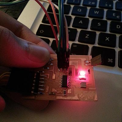
In the example above I was using the PCINT0_vect to manage the interruption of the on-board button. Luckily, last week I added two extra sockets in order to use the free ports if needed. Using a true hole button and a protoboard, I wrote a program that controls the falling and/or rising edges of the button connected to the INT0 pin. Using that information, the program blinks a led.
- //
- //
- // hello.ftdi.44.interrupt.c
- //
- // Neil Gershenfeld
- // 12/8/10
- //
- // (c) Massachusetts Institute of Technology 2010
- // Permission granted for experimental and personal use;
- // license for commercial sale available from MIT.
- //
- // Modified by Alejandro Escario
- // Mar 2015
- #include <avr/io.h>
- #include <util/delay.h>
- #include <avr/interrupt.h>
- #define set(port,pin) (port |= pin) // set port pin
- ISR(INT0_vect) {
- _delay_ms(10); // debounce timer
- toggle(PA7);
- }
- void toggle(int port){
- PORTA ^= (1 << port);
- }
- int main(void) {
- //
- // main
- //
- // the clock divider to /8 has been set with the fuses
- //
- // initialize output pins
- //
- DDRA &= ~(1 << PA3); // button as input
- DDRA |= (1 << PA7); // in-board led as output
- DDRB &= ~(1 << INT0); // interruptor as input
- //
- // set up pin change interrupt on input pin
- //
- set(GIMSK, (1 << INT0)); // enabling PCINT interrupts
- MCUCR |= (1 << ISC00); // Any logical request
- //MCUCR |= (1 << ISC01); // falling edge
- //MCUCR |= (1 << ISC01) || (1 << ISC00); // rising edge
- sei(); // enable interruptions
- while(1);
- }
Generating a controlled output signal might be useful in a near future to control output devices such us stepper motors. Therefore, I decided to spend some time understanding the Attiny44 timers.
This program uses a CTC timer to make two leds blink. One connected to the OC0A and OC0B ports. Additionally, it triggers an interruption that increases the OCR0A counter. This way the time between blinks varies. Once OCR0A reaches the 0xFF value, its value is changed to 0.
Both leds were blinking too fast to be appreciated by a human eye. I changed the fuses to divide the clock by 8.
- //
- //
- // hello.ftdi.44.ctc.c
- //
- // Neil Gershenfeld
- // 12/8/10
- //
- // (c) Massachusetts Institute of Technology 2010
- // Permission granted for experimental and personal use;
- // license for commercial sale available from MIT.
- //
- // Modified by Alejandro Escario
- // Mar 2015
- #include <avr/io.h>
- #include <util/delay.h>
- #include <avr/interrupt.h>
- #define set(port,pin) (port |= pin) // set port pin
- ISR(PCINT0_vect) {
- _delay_ms(10); // debounce timer
- if(~PINA & (1 << PA3)){ // falling edge
- OCR0A = 0x00;
- }
- }
- void toggle(void){
- PORTA ^= (1 << PA7);
- }
- ISR(TIM0_COMPA_vect) {
- if(OCR0A >= 0xFF){
- OCR0A = 0x00;
- }else{
- OCR0A += 0x01;
- }
- }
- int main(void) {
- //
- // main
- //
- // the clock divider to /8 has been set with the fuses
- //
- // initialize output pins
- //
- DDRA &= ~(1 << PA3); // button as input
- DDRA |= (1 << PA7) | (1 << PA2); // in-board led as output
- DDRB |= (1 << PB2); // led as output
- TIMSK0 |= (1 << OCF0A); // enable interrupt enable
- TCCR0A = (1 << COM0A0) | (1 << COM0B0) | (1 << WGM01); // CTC + Toggle on Compare Match
- OCR0A = 0x00; // initial pulse width
- TCCR0B = (1 << CS02) | (1 << CS00); // /1024 prescaling
- //
- // set up pin change interrupt on input pin
- //
- set(GIMSK, (1 << PCIE0)); // enabling PCINT interrupts
- set(PCMSK0, (1 << PCINT3)); // enabling the interrupts on PCINT3
- sei(); // enable interruptions
- PORTA &= (0 << PA2); // 0V on PA2
- while(1){
- };
- }
Using a PWM modulation, I wrote a program that changes the intensity of a led (connected to the OC0A pin) when a button is pressed.
- //
- //
- // hello.ftdi.44.pwm.c
- //
- // Neil Gershenfeld
- // 12/8/10
- //
- // (c) Massachusetts Institute of Technology 2010
- // Permission granted for experimental and personal use;
- // license for commercial sale available from MIT.
- //
- // Modified by Alejandro Escario
- // Mar 2015
- #include <avr/io.h>
- #include <util/delay.h>
- #include <avr/interrupt.h>
- #define set(port,pin) (port |= pin) // set port pin
- ISR(PCINT0_vect) {
- _delay_ms(10); // debounce timer
- if(~PINA & (1 << PA3)){ // falling edge
- if(OCR0A >= 0xF0){
- OCR0A = 0x00;
- }else{
- OCR0A += 0x10;
- }
- }
- }
- int main(void) {
- //
- // main
- //
- // the clock divider to /1 has been set with the fuses
- //
- // initialize output pins
- //
- DDRA |= (1 << PA2); // to be set as gnd
- DDRA &= ~(1 << PA3); // button as input
- DDRB |= (1 << PB2); // led as output
- TCCR0A = (1 << COM0A1) | (1 << WGM00); // phase correct PWM + on compare match
- OCR0A = 0xFF; // initial pulse width
- TCCR0B = (1 << CS01) | (1 << CS00); // /64 prescaling
- //
- // set up pin change interrupt on input pin
- //
- set(GIMSK, (1 << PCIE0)); // enabling PCINT interrupts
- set(PCMSK0, (1 << PCINT3)); // enabling the interrupts on PCINT3
- sei(); // enable interruptions
- //
- PORTA &= (0 << PA2); // 0V on PA2
- while(1);
- }
Another interesting language to program the microcontroller is assembler.
Using assembler instructions the programmer can control and explode all the microcontroller possibilities, and optimize the code. On the other hand, the programming process can become tougher and frustrating.
In order to get familiar with this language and microprocessor I decided to create a very simple program that turns on and off a led while pressing the button. This can be done within a loop or using interruptions.
- ;
- ; hello.ftdi.blink.44.asm
- ;
- ; Led + button -
- ; Alejandro Escario - FabAcademy 2015
- .include "tn44def.inc"
- .equ led_pin = PA7; led pin is PA7
- .equ button_pin = PA3;
- .equ led_port = PORTA; comm port
- .equ led_dir = DDRA; comm direction
- ; program is in lower part of memory
- .cseg ; code segment init
- .org 0 ; sets the location counter to an absolute value
- rjmp reset
- ;
- ; main program
- ;
- reset:
- ; set pin to output
- sbi led_dir, led_pin
- ;
- ; start main loop
- ;
- loop:
- sbic PINA, button_pin
- cbi led_port, led_pin ; set led pin
- SBIS PINA, button_pin
- sbi led_port, led_pin
- rjmp loop
My first approach was to use a loop, but I finally used an interrupt.
- ;
- ; hello.ftdi.44.blink.interrupt.asm
- ;
- ; Led + button (interrupt)
- ; Modified by Alejandro Escario - FabAcademy 2015
- .include "tn44def.inc" ; constant definitions
- .equ led_pin = PA7; led pin is PA7
- .equ button_pin = PA3;
- .equ led_dir = DDRA; comm direction 1 => OUTPUT (PORT) 0 => INPUT (PIN)
- .def temp = R16; temporary storage
- .cseg ; code segment init
- .org $0000
- rjmp reset ; sets the location counter to an absolute value
- rjmp 0 ; interrupt 0
- rjmp pcint0_handler
- ;
- ; main program
- ;
- reset:
- ; set pin to output
- sbi led_dir, led_pin
- ;
- ;interrupt enable for PA3
- ;
- ldi temp, (1 << PCIE0)
- out GIMSK, temp
- ldi temp, (1 << PCINT3)
- out PCMSK0, temp
- sei ; set Global Interrupt Enable
- cbi PORTA, led_pin ; set led pin
- loop:
- sbic PINA, PA3 ; if the button is not pressed
- cbi PORTA, led_pin ; turn off the led
- sleep
- nop
- rjmp loop;
- pcint0_handler:
- sbi PORTA, led_pin ; set led pin
- reti
At first sight, I knew that my project would need to use serial communications quite often. Taking into consideration the problems I faced with the echo example, the ATtiny44 might not be my best chance to develop the project.
The ATmega168 is. So let's build an Arduino board. I will be using the Fabkit model by now.
Once again the letters of the FabKit board were not milled as expected,... I will go on trying to solve that problem.
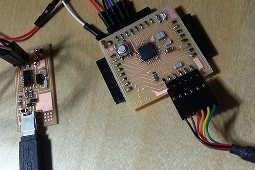
To check that everything works as expected, I loaded a very simple program (based on Neil's one) that makes the led blink as many times as the iteration of the loop that is being run.
- //
- // hello.arduino.168.blink.c
- //
- // test blinking LED
- //
- // Neil Gershenfeld
- // 10/21/13
- //
- // Modified by Alejandro Escario - FabAcademy 2015
- #include <avr/io.h>
- #include <util/delay.h>
- #define output(directions,pin) (directions |= pin) // set port direction for output
- #define set(port,pin) (port |= pin) // set port pin
- #define clear(port,pin) (port &= (~pin)) // clear port pin
- #define pin_test(pins,pin) (pins & pin) // test for port pin
- #define bit_test(byte,bit) (byte & (1 << bit)) // test for bit set
- #define led_delay() _delay_ms(100) // LED delay
- #define num_delay() _delay_ms(500) // Iteration delay
- #define led_port PORTB
- #define led_direction DDRB
- #define led_pin (1 << PB5)
- int main(void) {
- //
- // main
- //
- // set clock divider to /1
- //
- CLKPR = (1 << CLKPCE);
- CLKPR = (0 << CLKPS3) | (0 << CLKPS2) | (0 << CLKPS1) | (0 << CLKPS0); // 8MHz (CLK) vs 8MHz (desired freq) (scaling factor 1)
- //
- // initialize LED pin
- //
- clear(led_port, led_pin);
- output(led_direction, led_pin);
- //
- // main loop
- //
- int i = 0;
- int j = 0;
- while (1) {
- if(++i >= 255){
- i = 0;
- }
- j = 0;
- while(j < i){
- set(led_port, led_pin);
- led_delay();
- clear(led_port, led_pin);
- led_delay();
- j++;
- }
- num_delay();
- }
- }
This program made me realize that there was a problem: the led was not blinking. After reading multiple times the code and making sure that everything was OK, I got to the conclusion that there must have been a hardware error: the led was not pointing to the right direction. Once I fixed that problem, it started blinking properly.
I wanted to install the Arduino Bootloader. After configuring the IDE as described in the FabKit tutorial the bootloader was correctly uploaded. But when I tried to load the Blink example... I got an error:
avrdude stk500_getsync() not in sync resp=0x00
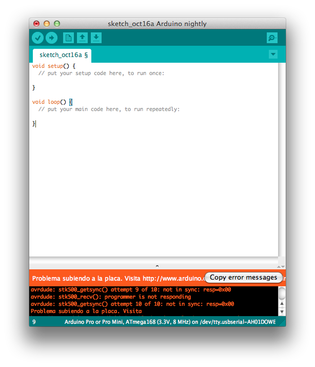
This error was a complete nightmare. Searching the Internet, the "solutions" I found were not fixing the problem. After trying to load the Bootloader and the program in several computers and getting always the same error, I solved the problem by running the Arduino IDE as the system administrator. To do that in MAC OS X (I am currently using OS X 10.10 - Yosemite) the executed command is:
~$ sudo /Applications/Arduino.app/Contents/MacOS/JavaAppLauncher
Then, the Bootloader and the program were loaded correctly. The strangest thing is that I don't have to open the IDE as administrator any more. Since I did that once, everything seems to be working perfectly.