Cyclops is a machine which consists of 4 Gestalt stages. Two of them shape the X axis, one the Y axis and the last one is the Z axis.
The building process was pretty straight forward. At first I cut and built each Gestalt using cardboard.
Once I got the 4 Gestalt stages built I started dealing with the software. I modified the single-node.py script (which can be found in the examples folder) until I was able to drive the 4 stages simultaneously.
I am surprised by its simplicity. I didn't get any major errors and got it working in a few hours.
In Fab Lab Madrid CEU there is only one student [me], so I decided to create an "unsophisticated" machine: a motorized pen [a very expensive pen]. In order to reach that goal, I designed two 3D parts:
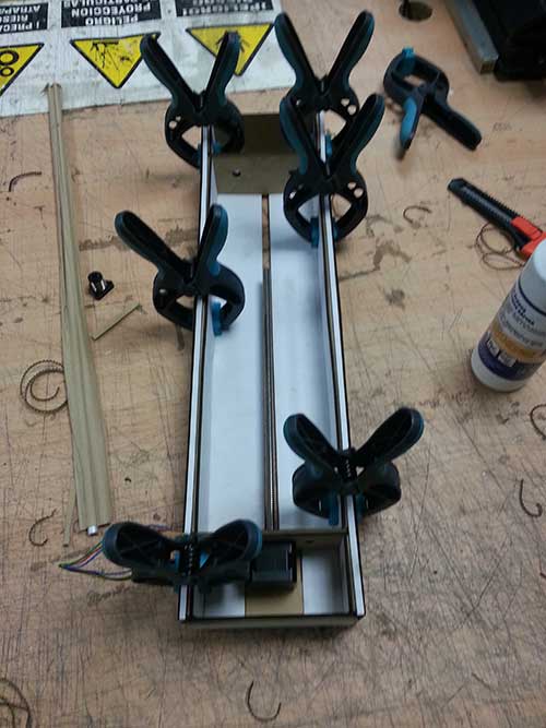
- Gestalt joint: 3D printed part which helps joining two Gestalt stages. Using this part is not mandatory, but highly recommended in order to distribute the load in the joint.
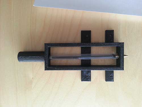
- Pen holder: 3D printed part to hold the pen. To improve the contact with the paper, I added a spring in the upper chamber.
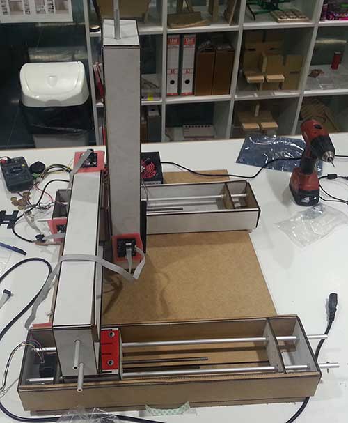
Then I started assembling all the different modules of the machine.
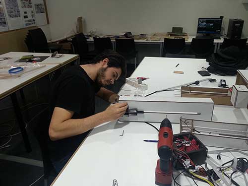
Until I finished the machine.
At first I wanted to move the "pen" using the coordinates extracted from a B/W image. But after researching a little bit and talking with my instructor, I decided to move it using a camera.
Using a camera to locate the position of the instrumental (a pen in this case) and finding the target position, takes the concept of machine controlling to a whole new level. This technique might lead to multiple benefits. One of those is that there is no need to do a XY zero before start using the machine.
A machine like this, can be useful in many areas, such as biomedical engineering, mechanical engineering, process optimization, etc.
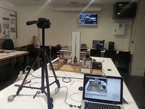
The first prototype of this machine consists of the 4 Gestalt stages with their corresponding boards, a Logitech C270 webcam and a few markers.
The machine is driven using a python program which receives real time coordinates from a server application. The server application records the state machine using a webcam, identifies the boundaries and recognizes the position of the pen. With that information, it is able to move the pen to a certain point inside the frame.
The server application uses ARToolkit to analyze the live stream and detect the position of the markers.
Once the program recognizes the position of the markers, it knows the XY zero position of the machine and can infer the destination position of the pen from a screen point.
Therefore, each time the user clicks on the screen, the program analyzes the image, calculates the relative movement to reach that point and, finally, sends it to the python program using a TCP socket.
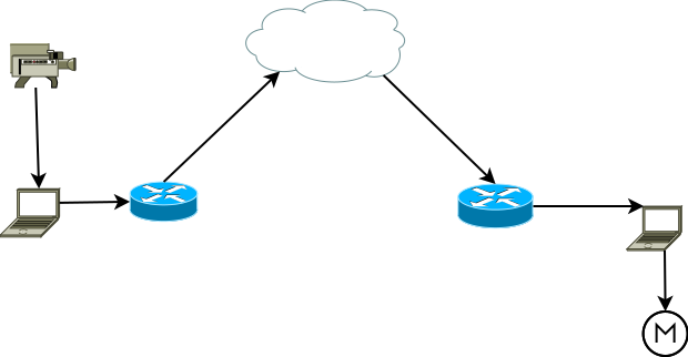
The C++ program (server) and the cyclops driver (client) are [currently] running in the same machine. But it could be running in different computers, even in different buildings, because it uses TCP sockets. To do that, just one modification is needed: instead of retrieving the video signal from a connected webcam, it must be streamed.
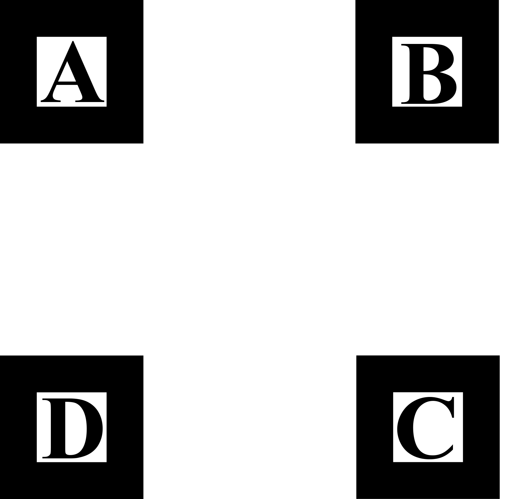
Identifying the boundaries and the pen position is not trivial. I used a library called ARToolkit, which analyzes a video stream in real time looking for the markers. In this example I am using two markers:
The first one consists of 4 markers separated by a known distance:
The second one consists of two markers separated by 10cm (from the upper left corner of the F to the upper left corner of the G):

Each single marker must be 4x4cm.
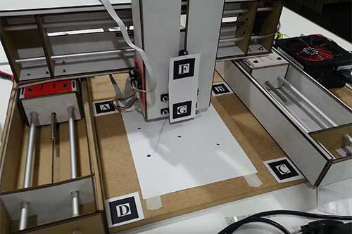
The position for each marker can be seen in the image above.
As seen, the webcam recognizes the markers and draws cubes over them. Those cubes are not necessary but help during the development process. The color cubes tells me whether the marker is being recognized or inferred or if the "pen" is inside or outside of the machine boundaries.
But, does it works?
Yes! In fact it works better than expected [once calibrated]. As seen in the video, the error introduced is about 2mm. That error is due to two factors:
- Perspective calculation: the calculation performed is based on 2D linear trigonometric using just one vanishing point.
- User: the user that is moving the machine using the mouse has to click on the place he wants to move the head to. The image low resolution is the greatest error.
The first error has two possible solution approaches:
- Dealing with 3D coordinates instead of 2D coordinates to determine the target position. To do that we need to calculate the XYZ position of a 2D screen point. To get an accurate position, a stereoscopic view might be needed.
- Using a higher resolution webcam and allowing to zoom in on the image to select the target point more precisely. Also a calculation using more than one vanishing points is encouraged.
Usage
The server must be executed prior to the client. The client program does not interact with the end user directly.
The server application can read some user inputs:
- Esc or q are two keys configured to close the program.
- Space (' ') key that toggles the z value from 0 to 15mm and viceversa.
- Left click creates a new destiny point.
- Right click (experimental) starts recording the mouse movement and creates a list of points to reproduce the movement in the machine. To stop recording, click again the right button.