Computer-Controlled Cutting
Laser Cut // Box Making and Editing + Laser settings
My goal for this module was to develop a tridimensional box in plywood with rounded corners in order to understand how to design notches on curved surfaces. I started thinking on how to work my object using a 3d modeling software. Afterward, I realized that my goal could have been accomplished also design with a cad in 2D.
Before using a CAD, I first understood the general dimensions of the bounding box of my idea. Indeed, the firt element I designed has been a simple box 18x36x18 cm.
I switched on the website of
Box Maker Connection Lab to generate my initial box.
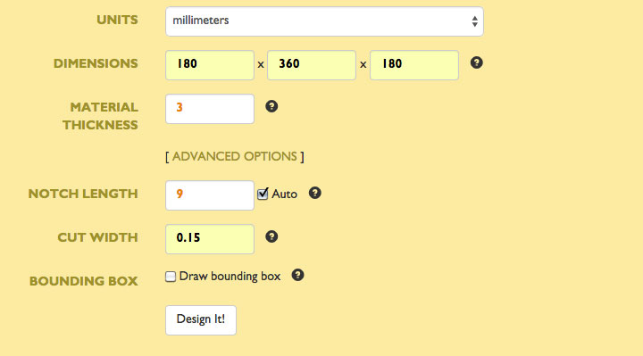
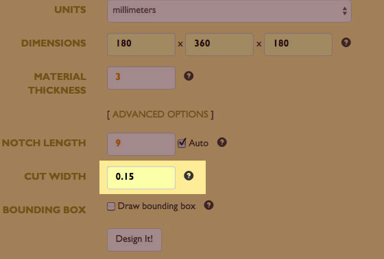
I put all the information about my box in the tabs like in the following image:
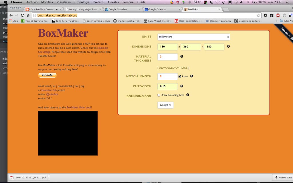
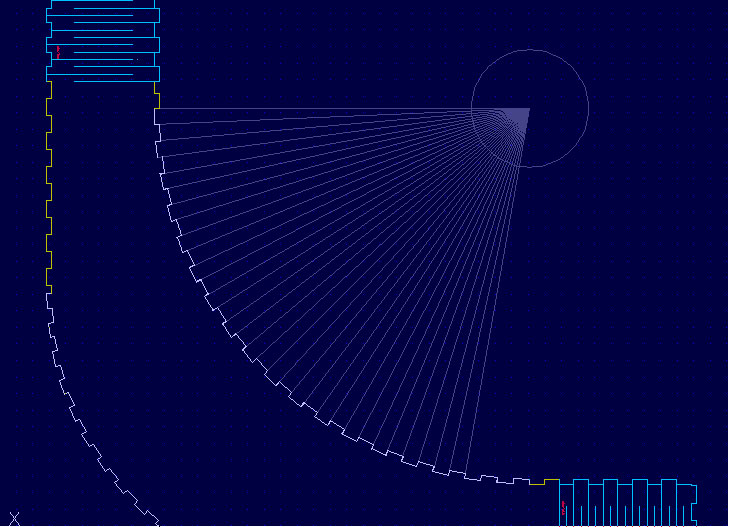
I payed attention to the thickness of the availabe material (plywood 3 mm thick), the notches lenght and the cut width (I use an Epilog and the hypotesis was that the cut widht is 0.15 mm). To understand how to set the notches lenght I first worked on the CAD on the curved part of my object and projected by the centre of the circle generating the first curved notches that were about 9 mm lenght. I set the same lenght for the straight notches on the web app.
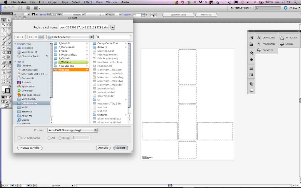
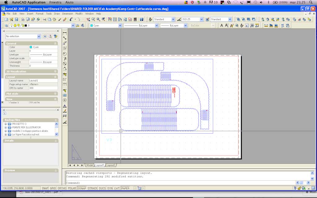
The software generated a pdf file that I opened in Illustrator and exported as dwg file in order to work on it in Autocad. Infact, to do this job, I needed a tool highly precise, and, since I had few hour to accomplish my goal, I decided to use the one I know better, that is Autocad.
I have a background as an architect that allows me to easily work in 2 dimensions to create elements that will compose a tridimensional outputs, most of all if they are simple as the object I wanted to create for this module. I work with section and projections instead of makind 3D models to create 2D elements. In this case I worked as well in this way: working in 2D allows me to master all the elements in a faster way than using 3D modeling. And for this kind of project I didn't really need to work 3Dmensionally.
In Autocad I worked mainly on three aspects: bending pattern for curved faces, notches fitting and position for bending faces and notches dimension in order to make the element solid without gluing it.
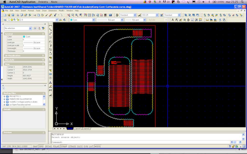
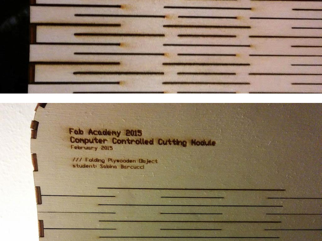
As the image above shows, I used a color code to distinguish the several elements that had to lock together. So: notches coloured in magenta have to fith notches magenta and so on. I also wrote with a microscopic font the position of the elements for the assembly phase. Once finished the first version of my object, I printed the dwg file with a PDF printer on a scale 1:1, inscribing all the elements in a rectangle with the same dimensions of the Laser Cutter Epilog.
The last passage has been done in illustrator where I edited the lines to be cutted of my drawing. Following the settings I used to edit the lines and to set the Laser Cutter Epilog Legend 36, 60 Watts
////// Lines Settings
CUT
line color black (RGB 0,0,0)
line stroke 0.01 mm
ENGRAVE
fill color red (RGB 255, 0 0)
////// Epilog settings
Color Code
(cutting) RGB 0,0,0 / Speed 30; Power 80; Frequency 500;
(engraving) RGB 255, 0, 0 / Speed 80; Power 60; Frequency 500;
Press Fit Construction Kit
I previously set the notch lenght on 9 mm. To create my press-fit construction kit I started adding to the online customizer "BOx Maker Connection Lab" the cut tickness of the EPILOG laser I used for cutting the bending object, which is 0.15 mm. This is the divergence between the teeth that protrude left-and-right which is called kerf and it defines the width of the saw cut.
Each laser has its own kerf. This is a kind of information that the machine retailer should provide you otherwise you can determine this measure empirically, making different cuts and using a caliber to understand how ticjk is the cut width.
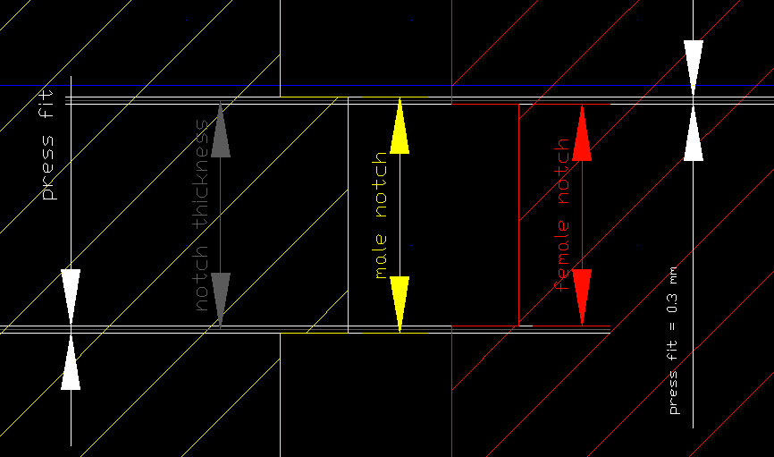
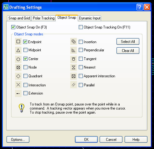
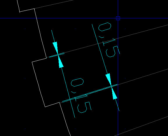
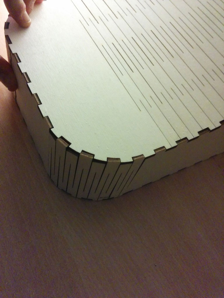
This is how I basically operated: making "male notches" 0.15 mm larger on each side, and making "female notches" 0.15 narrower in order to create an overal interference between notches of 0.3 mm. Using a plywood material this interference still allows a good press fit. Using a stiffner material could probably not to allow notches to interlock each other. The dimension indicated as "notch tickness" is basically the 9 mm average lenght I set in the box maker web customizer. For the curved elements, the issue was a little bit more complex and I managed it in this way. As for designing the notches along the curves, I first designed a curve and then divided it into little modules in as many pieces as dividng the line in modules ore or less 9 mm long. Then I fould a common center of projection and derived 3 mm tick and about 9 mm long notches. This operation requires to be veruy precise. To make if faster, it is necessary to set up OBJECT SNAPS as in the below image. This settings work not only in Autocad software but in any CAD you choose to use.
As for the other notches, I used the same method: adding 0.15 mm to the male notch lenght on each side (0.3 in total) that means subtracting 0.15 mm each side of the male notch.
Prototyping Test and Retry
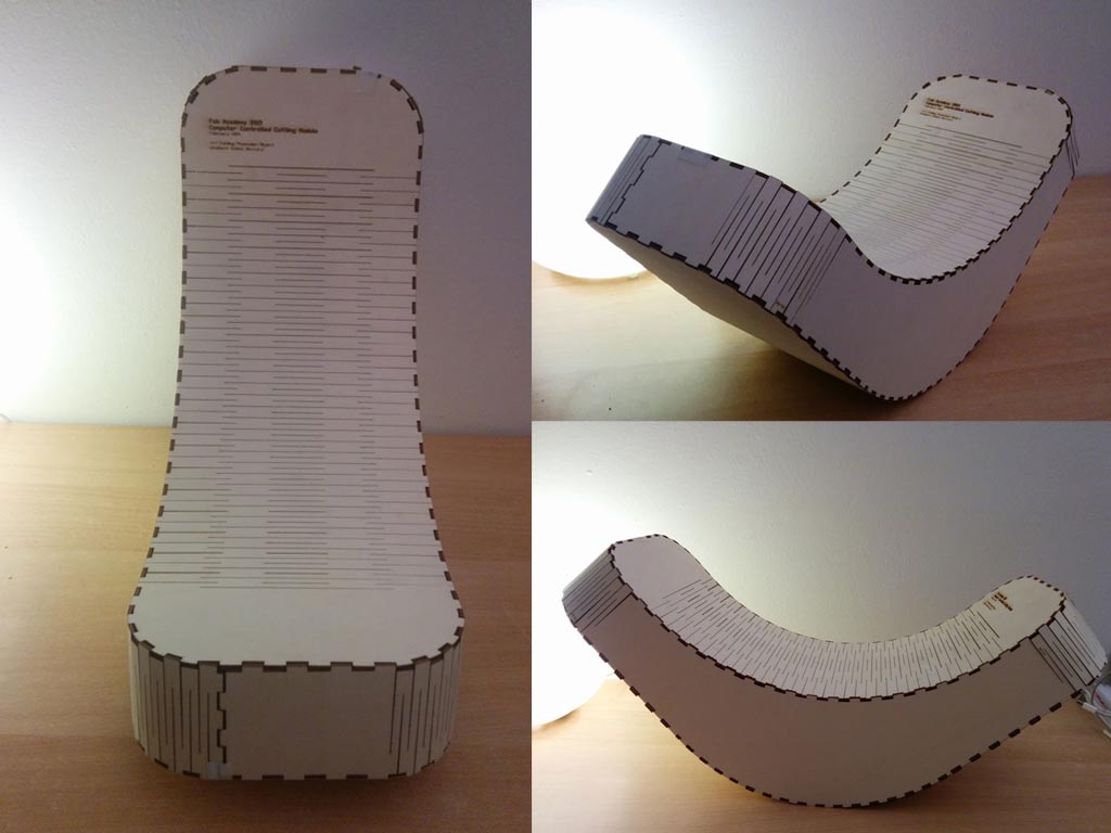
The first prototype coming out from the laser wasn't working at all. It needed a lot of tape to stay together and the bending pattern wasn't performing good. In particular, the bending pattern was very fragile and very stiff.
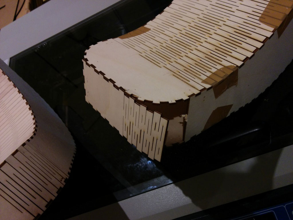
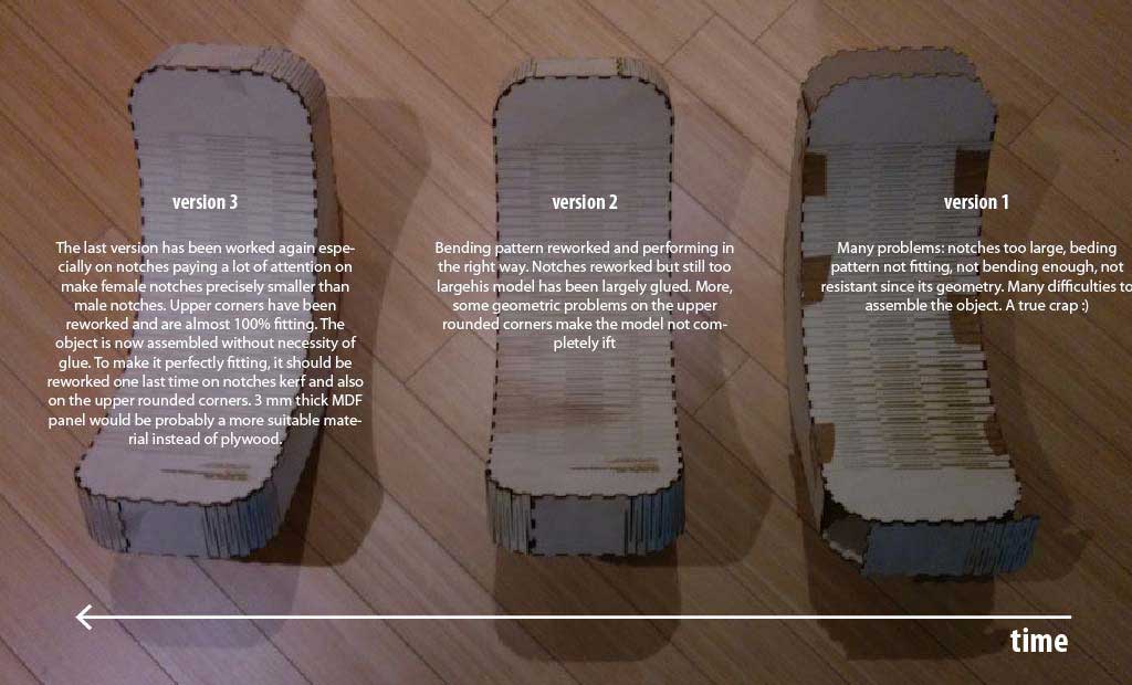
With the physical prototypes I was able to quickly understand the most of my problems. I retried with a new version and then a third.
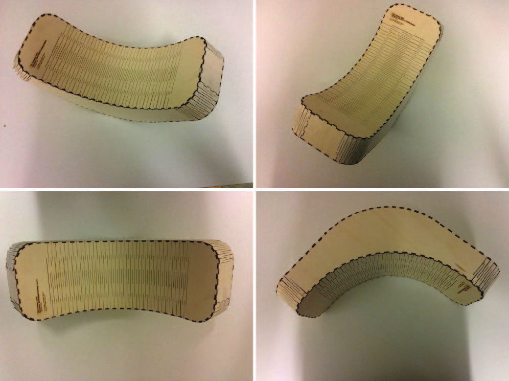
Below the first and the last bending for a confrontation and a details of the curved notches on the bending wood.
Following a recap of my tests until the last version (the third) that I consider the last one. The elements don't require anymore glue to fit. In any case, a fourth version of the object with larger notches would be preferable.
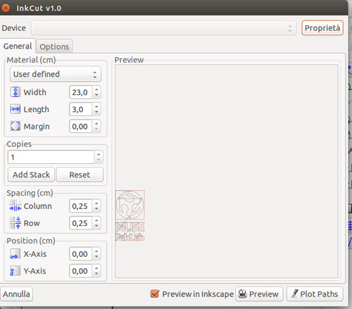
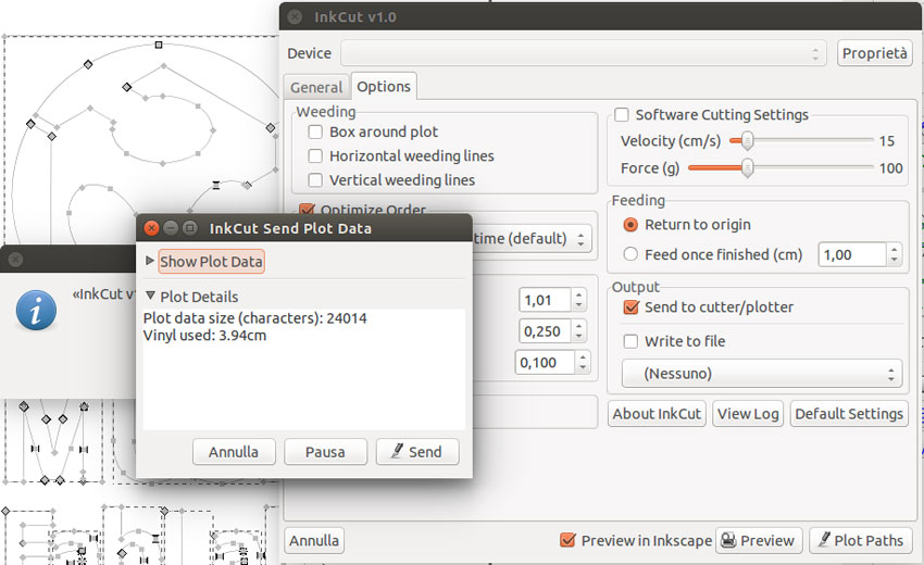
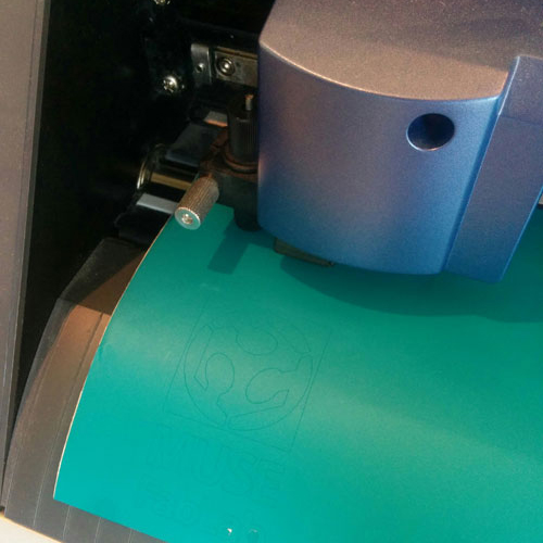
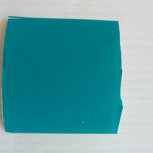
Vinyl Cut // Cutting the MUSE FabLab logo

