Week 16::mechanical design, machine design
Assignments:
- make a machine, including the end effector build the passive parts and operate it manually, document the group project and your individual contribution
- automate your machine, document the group project and your individual contribution
1. Group assignment
This week assignment consists of creating a machine, document the group project and your individual contribution
Team (FabLab León):


This assignment was a group assignment and we had to use 4 modules since we were 4 of us. Firstly we had a brainstorming to know exactly what we’ll build and how we’ll implement everything together. We knew it from the start that we would try to build a full 3 axis machine, but our 4th module was a little bit out of the line and didn’t really knew how to implement it in our machine. Apart from the 4th module we had to take in consideration the actual machine and be sure to build a functional and stable prototype. Following this idea and taking in consideration only 3 modules we couldn’t find a functional, nor stable way to build our machine. Naturally, we reviewed again the available information from the mtm website and we started to play with the presented ideas: 2 integrated modules for the base of our machine. This idea resulted useful since it presented stability and horizontal movement by moving those 2 modules at the same time. From this point forward we almost had our final idea defined: the 2 modules conferred our y axis movement, one transversal module conferred our x axis movement and finally a vertical module conferred our z axis movement. We had the full 3 axis movements defined and all the 4 modules integrated. Onwards, we had to define the purpose of our machine and we have choose to design and build a machine that can draws shapes on paper. Great, we had everything defined and ready to build our drawing machine.
Presentation Slider:
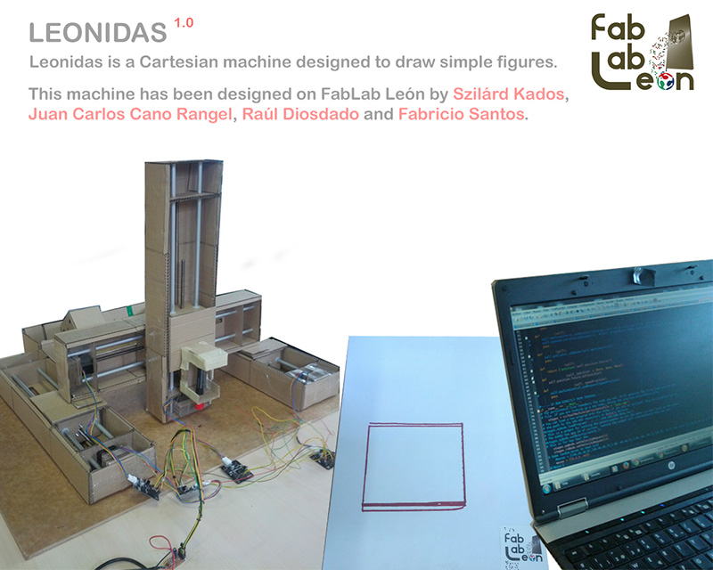
2. Description of the modules and design of the structure (Fabricio Santos)
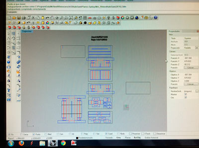
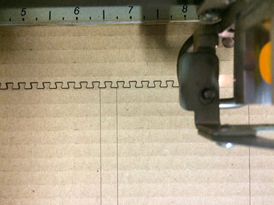
We need to build 4 modules so we prepare the model in order to be cut in the laser cutting machine. But our machin e was smaller than the unroll pieces we need to cut; so we had to split the model to be cut by using a kind of press-fit zipper made by Nadya and then we join it and stuck with cellotape.
Preparing cut:
Laser Cut:
For the material we chose a 3 mm thickness cardboard and we cut it in an Epilog Mini Laser 40w. So we use this cutting parameters: (speed/power/dpi) blue: 60/50/1000 (cutting) red: 100/15/500 (engraving)
assembly 1:
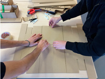
assembly 2:
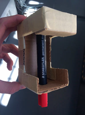
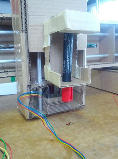
Then we design a cardboard tool to hold the pen in the Z axis. So we design it the unroll surface of the model, we cut it and then we stuck its flaps in order to give it enough stiffness to bear the pressure of the vertical axis at the tip of the pen.
3. Machine description and assembly (Szilárd Kados)
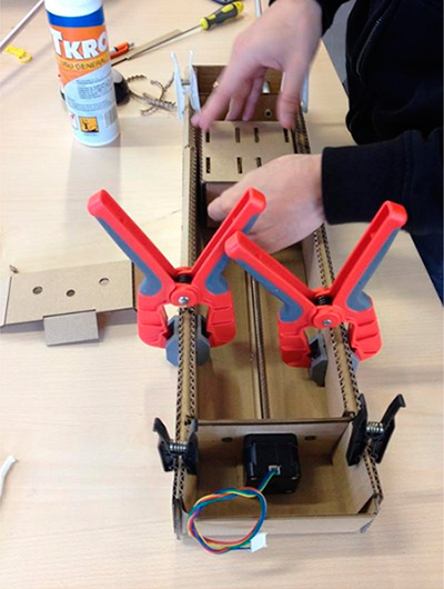
This assignment was a group assignment and we had to use 4 modules since we were 4 of us. Firstly we had a brainstorming to know exactly what we’ll build and how we’ll implement everything together. We knew it from the start that we would try to build a full 3 axis machine, but our 4th module was a little bit out of the line and didn’t really knew how to implement it in our machine. Apart from the 4th module we had to take in consideration the actual machine and be sure to build a functional and stable prototype. Following this idea and taking in consideration only 3 modules we couldn’t find a functional, nor stable way to build our machine. Naturally, we reviewed again the available information from the mtm website and we started to play with the presented ideas: 2 integrated modules for the base of our machine. This idea resulted useful since it presented stability and horizontal movement by moving those 2 modules at the same time. From this point forward we almost had our final idea defined: the 2 modules conferred our y axis movement, one transversal module conferred our x axis movement and finally a vertical module conferred our z axis movement. We had the full 3 axis movements defined and all the 4 modules integrated. Onwards, we had to define the purpose of our machine and we have choose to design and build a machine that can draws shapes on paper. Great, we had everything defined and ready to build our drawing machine. Fabricio already was cutting out the cardboard for the modules, Raul was preparing the electronics, Carlos was familiarizing with Gestalt and I started to fold, glue and prepare the modules for the machine. Folding the modules were tricky since it needed special care because of the material (cardboard) and even so it wasn’t as consistent as we would expected. For every module I made I have tried to improve folding or make it better, stronger as the last one. With this learning by doing technique the first folded module came out the worst and the last one the “best”. These modules needed to be strong enough and to present consistent / smooth internal movements. Since we are talking about cardboard these modules were ok, but far from perfect.
assembly 1:
assembly 2:
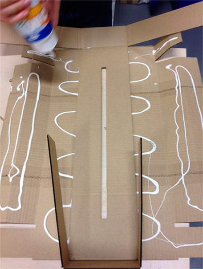
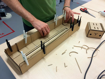
After the 4 modules were prepared we have started to build our machine, to fit together these modules. We used an MDF sheet as of the base of the machine and glued 2 modules horizontally, taking special care to glue them parallel to each other. Glue another module transversally to the moving pieces of the first two modules. And glue the last module vertically to the moving piece of the 3d module. With this we had the base structure of our drawing machine, but still we were missing one important part: the marker holder. This holder we made it from cardboard and on the fly, simply cutting cardboard with a cutter and taping it together. In the end everything came out quite nicely and it was ready for the electronics and program executing.
assembly 3:
assembly 4:
4. Electronic control (Raúl Diosdado)
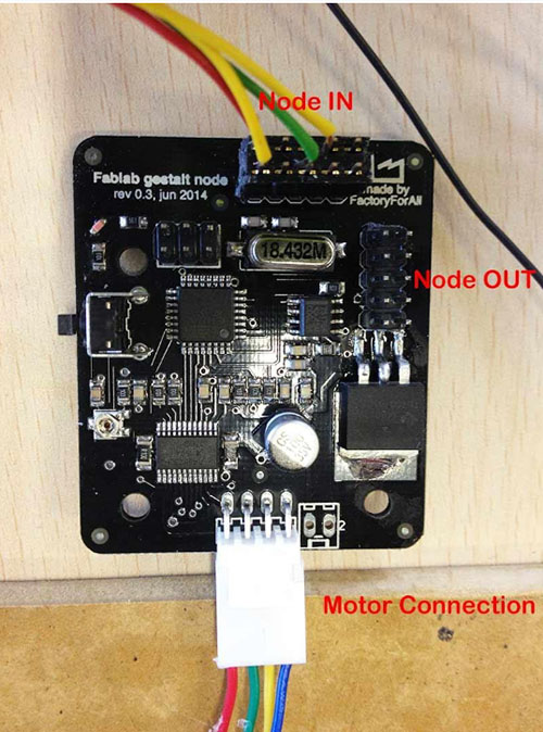
The electronic controller of the machine consists of nodes "Gestalt", the machine will have many nodes as motors have to control. This is one of the Gestalt nodes:
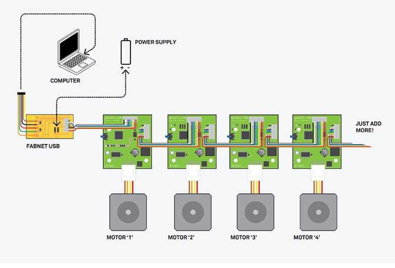
The communication between the computer and the nodes is done in series, so that all nodes are interconnected, can be added as many nodes as you want, you only need to add at the end of the last node. The resulting configuration looks like this:
As shown in the picture above, you need to create a board that bridges between the computer and the first node. This board is used for transmitting nodes both information and power to the engines.
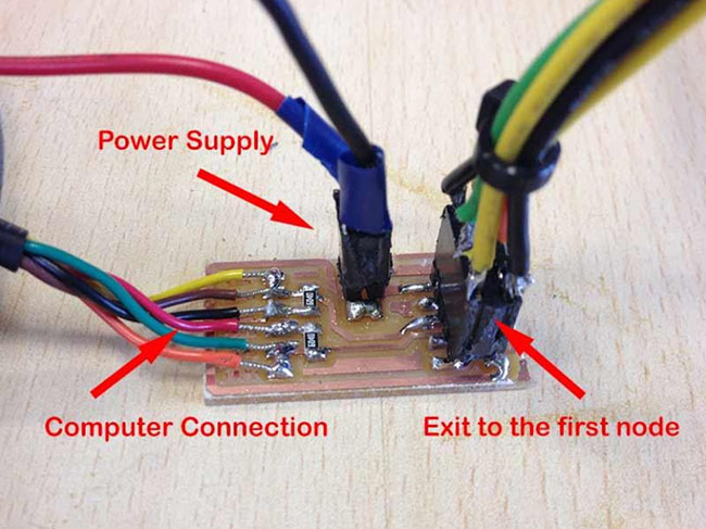
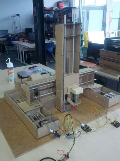
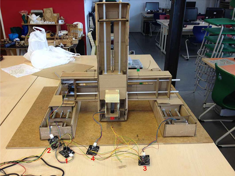
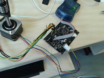
In the "Source files" you can find the file to make this board. In the next picture you can see the mounted machine with each of its nodes numbered
Problems with electronic When performing tests with the machine we detect a slight problem with electronics, the driver power that feeds the engine overheats, we realized that some projects had already made heat sinks to solve this problem, but we we did not have heat sinks in the FabLab at that time, so we regulate the power that is given to the engine regulating it in the potentiometer.
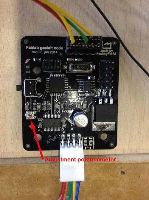
We have set the current around 150mA, more than enough power to move the motors
5. Programming the modules(J. Carlos Cano)
In the task group, at the beginning we have had many problems and questions with the mcm, gradually were solved thanks to the documentation available on the Internet from other projects and feedback through the mailing list of the Fab Academy.I Have paid attention to all parts of this project in which my colleagues worked, but my mission within the Group has been learn to communicate various kits and investigate about the programming of these devices.
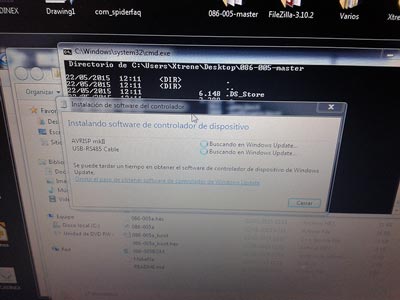
Drivers needed for comunications:
Connections:
We have lost enough time trying to load the bootloader on the supplied boards, we finally got it, then realised that it was not necessary, as the board come with the firmware already installed.To load the boot loader is necessary to install the USB-RS485 cable drivers and drivers of the programmer (AVRISP mkII), in my case, both were installed automatically with windows 7. I did the same actions in Kubuntu 14.10, to install the FTDI cable drivers downloaded drivers from http://www.ftdichip.com/Drivers/VCP.htm and the AVRISP programmer mkII didn't install anything. We can find the bootloader source code at the following address: https://github.com/imoyer/086-005. Once downloaded and uncompressed we accede to the newly created folder and in command line to load the bootloader I wrote the following:
cd 086-005-master Nano Makefile
look at some options that has this file, at the end we can read:
program-avrisp2 # uncomment to bootloader program #avrdude - e - c avrisp2 - P usb - p m328p - U flash:w: 086-005a_boot.hex # uncomment to program application avrdude - e - c avrisp2 - P usb - p m328p - U flash:w: 086-005a.hex
This Defaults configuration did not work for me, once loaded the bootloader can't could communicate with the board via the supplied python scripts. I modified the code in the following way to reprogramme the bootloader:
program-avrisp2: # uncomment to bootloader program avrdude - e - c avrisp2 - P usb - p m328p - U flash:w: 086-005a_boot.hex # uncomment to program application # avrdude - e - c avrisp2 - P usb - p m328p - U flash:w: 086-005a.hex
Now communication is correct.
sudo make program-avrisp2-fuses sudo make program-avrisp2
As I said above, is not necessary (usually) load the bootloader on the boards, from this point I started to investigate the way to communicate with the board from the PC. First we must install Python 2.7, pip (for linux install of pyserial) and pyserial. Since Python 2.7.9 + (released December 2014) ship with Pip.To install pyserial: - Windows: download and run the installer from the following link: https://pypi.python.org/pypi/pyserial - Linux: Run on a terminal:
sudo pip install pyserial
Machine: Leonidas from FabLab León on Vimeo.
Files: