CLASS NOTES
Machine Design
A 4-axis milling machine for jewelry
Summary
Concept
For this assignment we decided to solve a practical problem from our local community, so we can take this as an opportunity for doing research on a project that could have some later reuse.
Our idea is about building a 4-axis milling machine especially designed for working on wax rings. This came from different requests we had here at Fab Lab Cascina from people working in jewelry to achieve a better precision than sculpture done by hand and 3D printing.

The machine is quite compact, so it can sit on a desktop and as already mentioned has four degrees of freedom: a rotating axis for rings, an X movement perpendicular to the ring radius, a tilting head rotating about 15 degrees on each direction and a Z axis for moving the milling tool up and down.
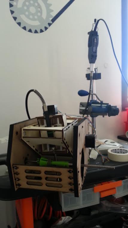
For the milling we decided to use a popular Dremel drill with an extension cord, mostly to reduce the moving head weight.
Requirements and Planning
The planning for the project was centered on requirements:
- Create a small, easy to use machine for wax ring milling
- Allow to have different ring sizes
- Be able to mill all around the ring surface
- Support commodity spindles like Dremel or precision tools common in jewelry applications
Then we defined milestones, the bold one have been checked as date of writing:
- M1. Research existing solutions for milling wax rings
- M2. Develop an overall concept for the machine based on research findings
- M3. Define tasks and responsibility for building the machines, we have one student responsible for each of the following:
- Overall mechanical architecture
- Building the parts using lasercutter and 3d printer
- Setting up the electronics and programming it
- Prepare a GUI for controlling the machine.
- M4. Learn the Gestalt framework and test the boards
- M5. Assemble the mechanical structure of the machine
- M6. Setup the controller
- M7. Prepare a basic UI
- M8. Integrate all.
Individual contributions
- Giacomo Falaschi Overall mechanical architecture and design, machine assembly
- David Montenegro Building the parts using lasercutter and 3d printer, enclosure design
- Francesca Mereu Setting up electronics, programming, ring holder design
- Troy Nachtigall Designing custom electronics (see later), UI interface design
NOTE: Individual contributions pages are not yet online and will be coming in the next few days, before July 1st.
Research
For better understanding the mechanical requirements of a similar machine we rely on existing designs available on the internet.
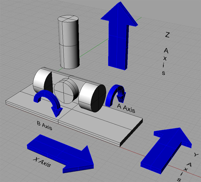
In particular we found very useful the CncCookbook site, for understanding different motion schemes when more than the standard 3-axis are used. In our case we started from the following diagram, just removing on of the five axis.
Development
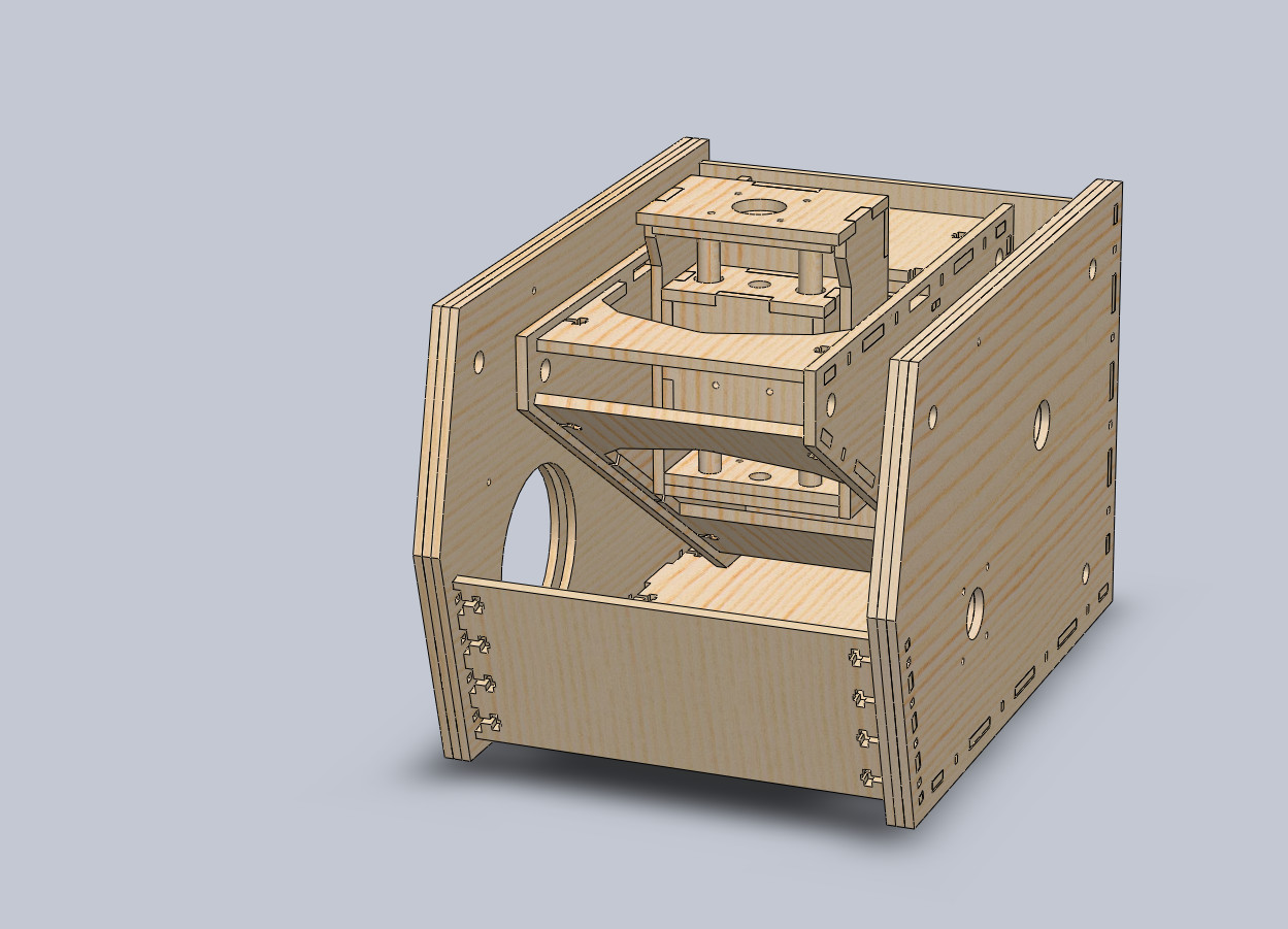
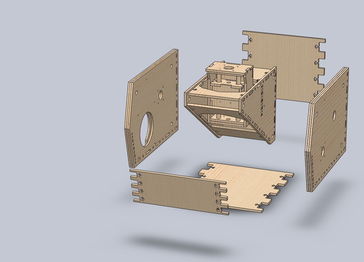
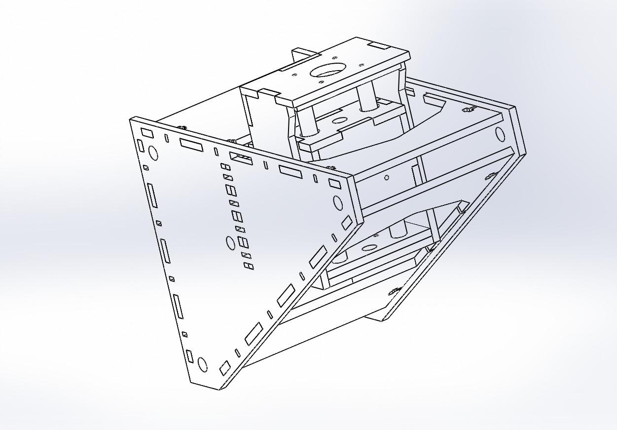
Mechanical design
The mechanical part of the machine had a quite smooth development cycle. We started from Solidworks models and then quickly moved into the actual prototyping using the laser cutter. We mainly used wood rather than cardboard to achieve a greater weight for the structure, aiming at a very stiff machine.
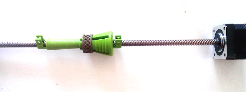
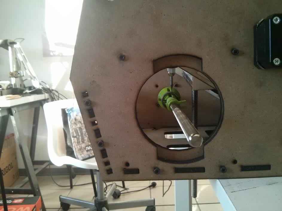
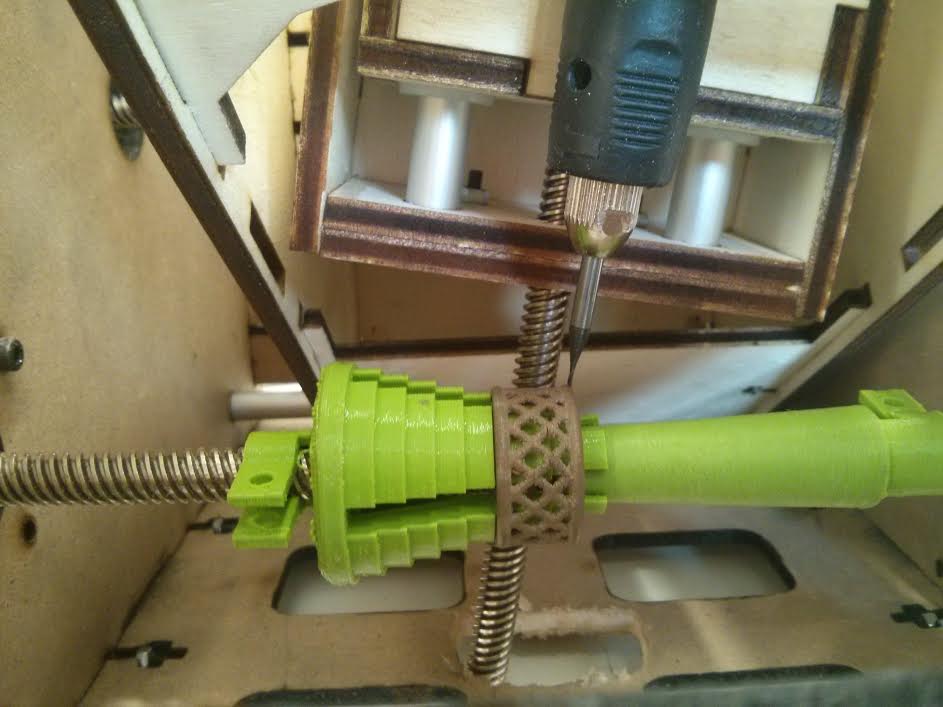
Ring holder
A specific task was on our agenda about the ring holder, which we developed in 3D and produced using standard FDM 3D printing. The reason for this was to allow us rapid iteration on this crucial part design, which was inspired anyway by existing solutions.
Trouble with gestalt
On the electronics we had significant trouble with the Gestalt modules, like many other labs. Still today we weren’t able
to have any Gestalt node working.
As troubleshooting we performed the following:
- Test with several cables
- Debug signals with an oscilloscope
- Reflashing board firmware
- Rewire everything following other labs indications
- Program the boards with simple blinking code
The main problem was boards were not blinking with gestalt code, while perfectly working with our code and accepting firmware updates.
Making our own nodes
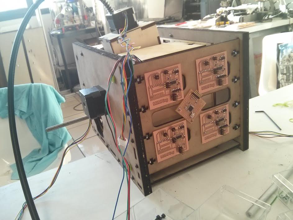
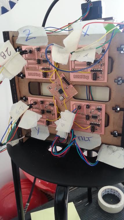
We had to decide an alternative approach for designing the machine, in particular we opted for a simpler star-architecture using a FabKit controller as the main gateway for communicating with the computer and four extension boards using ATTiny44 that control Pololu breakout drivers. All communication would happen via RS232 serial protocol.
Here are shown the custom boards with RS232 star-architecture
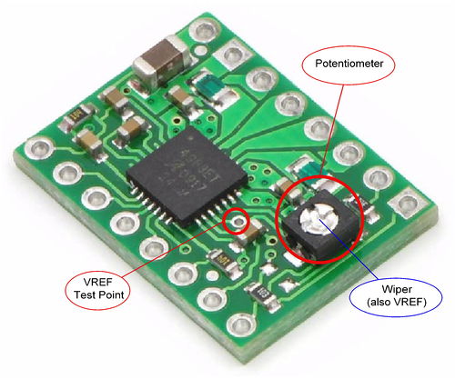
The Pololu breakout boards look like the following:
These boards, very popular in the Reprap world are simple breakouts for the Allegro A4988 Stepper Motor Driver Carrier, which takes care of most of the requirements for controlling stepper motors. They are mass produced in China and can be found online for 2-4$, so are almost as cheap as the standalone IC found in the inventory, still available everywhere in large quantities (we had more than 10 in the lab). One of these is soldered on the back of each extension board.
The documentation for the chipset used can be found here
Control Software and GUI
Since moving to our custom boards, we are a bit behind on the schedule for the GUI software and controller. Given we have now our own boards, we’ll probably rely on adapting a G-CODE interpreter like GRBL to be running on the main node, and talking to custom firmware on the extension boards with a packet based serial protocol.
Once GCODE can be read by the main node, we’ll adapt Fab Modules for the GUI part.
Conclusions
We knew that the project, given the available timeframe, could not bring us to a complete machine. Even with this in mind the amount of work for making this first prototype was significant. Having to also design the electronics and rethink a controller framework has also influenced our schedule, leaving little time even for preparing a demo.
Still a lot remains to be done:
- most of the code for the controller needs to be written
- integration with Fab Modules as a user interface needs to be done
- test should be made with real milling jobs
- the machine design needs to be improved especially in parts count
- 3d printed parts should be replaced with suitable aluminium or casted metal
Producing this machine has taught us a lot in terms of team work and effort planning, but was rewarding at least in the fact that we produced a working mechanical design which can be a basis for further development and possibly a much broader open hardware project with some practical applications.
Downloads
Due to large sizes the files are hosted on github.
You can find them at https://github.com/ifala/m2m_ring.