Machine Building - Fablab Amsterdam - Fabacademy 2015
Building a CNC hotwire cutter
Assignment: make a machine, including the end effector, automate it document the group project and your individual contribution
Assignment: make a machine, including the end effector, automate it document the group project and your individual contribution
In order not to create another machine to end up on a machine graveyard, we decided to create a machine that Fablab Amsterdam doesn’t have yet, but would be useful. Our goal is the make a CNC hotwire cutter with 4 degrees of freedom.
When we decided on our plans we had a meeting to figure out what needed to be done, what had first priority and who would work on what. We made a pirate pad to keep track and started by getting all the materials in. For sure it wasn’t complete, but enough to get started and get things going.
We decided to fabricate a computer-controlled 4 axis hot wire cutter. After discussing how the machine should work and which additional materials we would need, Till’s first job was to fetch
The microswitches would be connected to the Gestalt nodes and used to calibrate each axis. Till bought all materials at Rotor Amsterdam. The microswitches were quite costly.
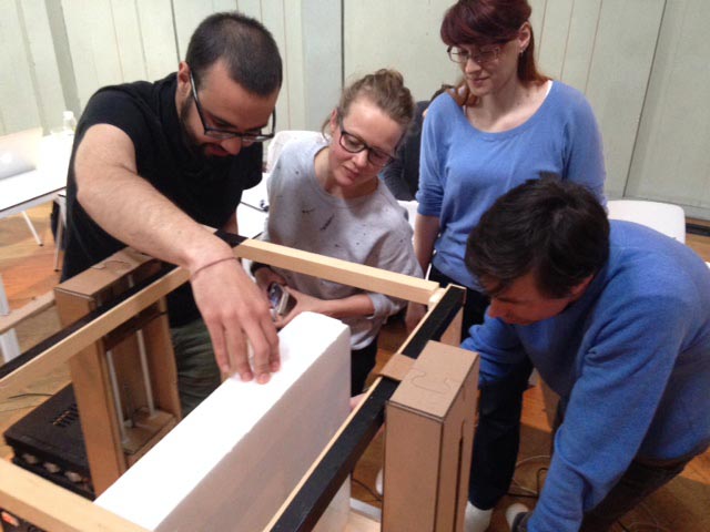
Back at the Waag, Till set up an environment to test if the wire properly cuts. He looked for some appropriate connectors for the power supply and found some prefabricated cables w/ crocodile clips and appropriate connectors for the power supply. So, he didn’t need to make the cables. Till sawed two wooden sticks of approx. 20 to 30 cm lengths and wrapped the wire’s end around the sticks’ ends. He fixed the sticks using the workbench’s holes and connected the wire to the power supply with the cables. The product sheet stated that the wire would be hot 100 °C at 4 Ampere. Together with Alex and Henk, he tested the hot wire cutting. They smoothly cut some foam with about 2 A and 5 to 6 V.
Before we run the entire cut sheet we ran a few test cuts so that we could get the values right. Correct laser cutter settings: For cutting: speed 2.7 power 100, and for score lines: speed 10.0 power 100
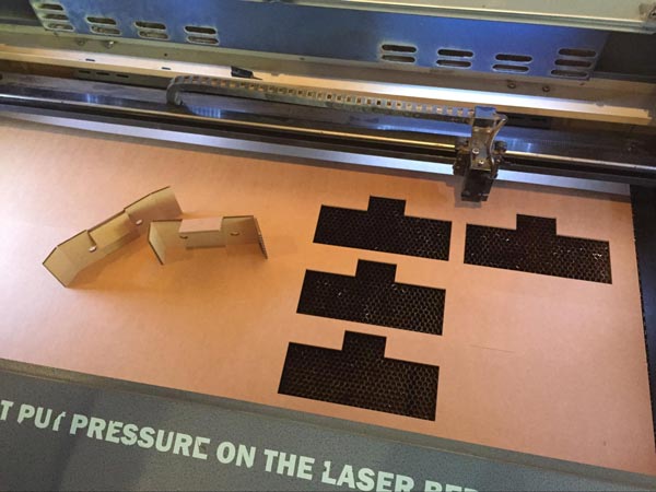
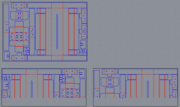
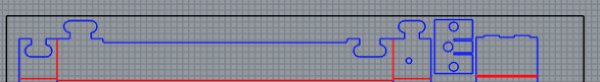
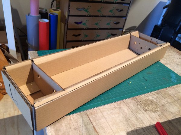
The cut sheet had to be divided into a two job cut as the body of the stage was larger than the laser bed. Joe used Rhino to split the original cut sheet into two. The top sheet is the size of the cardboard purchased and the bottom two are the size of the laser bed. Plan was to insert the large piece of cardboard and cut it, then turning it around and cutting the other half.
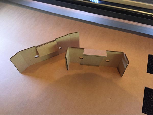
This wasn’t precise enough though, so we made two seperate parts that connect like a jigsaw puzzle:
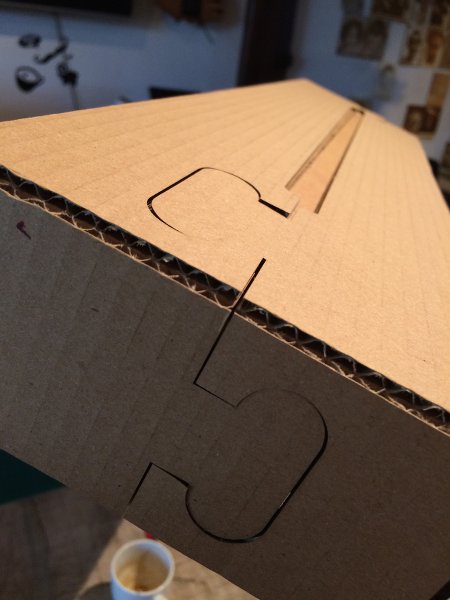
While assembling the test body of the stage we noticed that some parts were a bit tight, so we took a few millimeters off in the cut file. While assembling the moving part within the main frame, two cardboard ‘flaps’ overlapped by 10 millimeters, so we reduced that size as well.
There were several other issues we encountered;
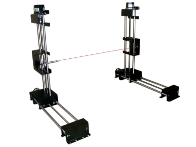
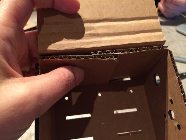
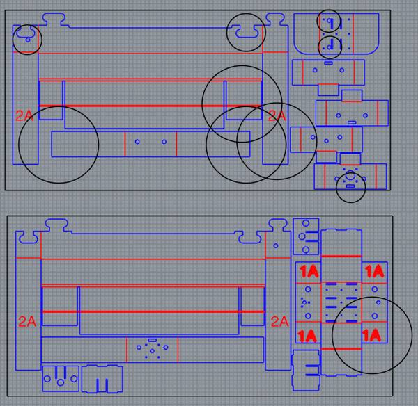
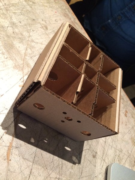
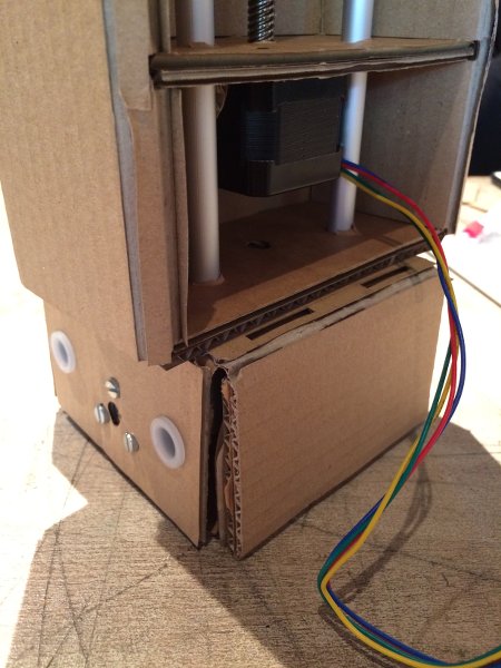
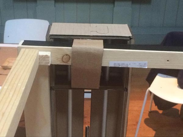
Unlike in the animated GIF, there are no holes for the rods to go through to the outside of the stage. We do want them to go through, because we found that the extra length of the rods can function as a connection between the horizontal and the vertical stages, like the picture below. This is why we added two holes into the top of the moving part of the horizontal stages.
We also added additional holes in the cut files to accommodate 8 end switches, so we’ll have end stops on both sides of all axes. Finally, we adjusted the housing to accommodate the range of the servo motor, so that the moving part will actually hit the end stop.
Now, let’s cut and build some stages!
Instead of the yellow glue, we tested the 3M Photo Mount as an adhesive to stick some of the cardboard flaps together. It dispensed evenly and worked quite well.
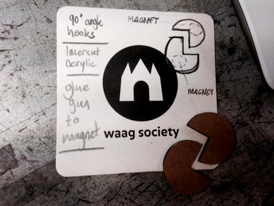
This was the original plan, but we didn’t implement it yet. Now we are using doublesided tape and a wooden cutting bed. We had to create a bed to put the foam on and to keep it in place. We will be using an aluminium bed and are making two magnets with a 90 degree angle hook on top, to keep a square block of foam in place. The hotwire really melts through the material so should be enough to fasten the material easily. This is also how it’s done on other machines.
Since the stages are finished, we’ve been able to determine the size of the maximum cutting hight and length at 28cm. We then decided on the size of the bed: 28 x 56 cm, to allow for bigger pieces of foam to be cut. If the bed would be wider, the angle that can be cut will be smaller.
X = 28, Z = 28, Y = 56
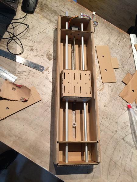
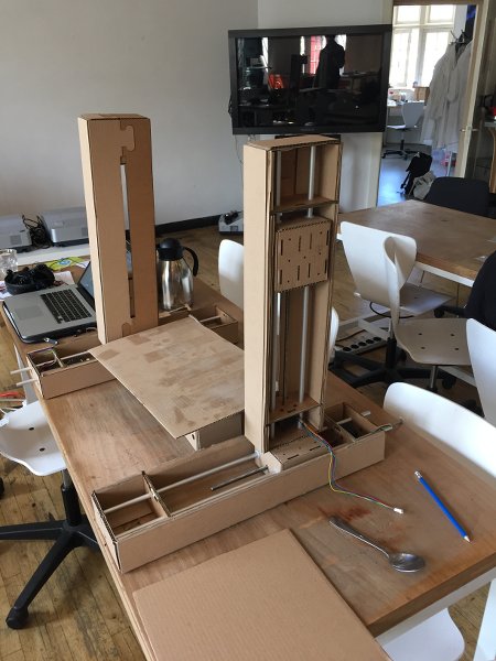
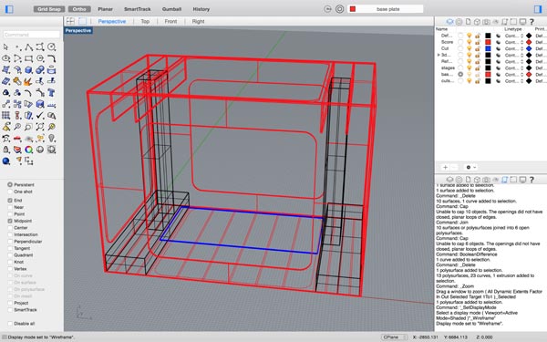
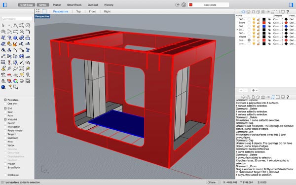
When designing the housing for the machine we need to take into account the hight and size of the bed (how to raise and secure it) and how to secure the stages so they don’t move if the wire is stressed. We’re thinking of an Ultimaker-like construction but press-fit, that integrates a base that fixes the bottom stages and raises the bed, and also fixes the pillar-stages so that they can only move along one axis. We used the cut sheet to extrude the stages in Rhino 3D and design the box around it. Next up is designing all the parts including the joints to fasten the box. We bought a large sheet of 5mm plywood to cut the box with the shopbut later on.
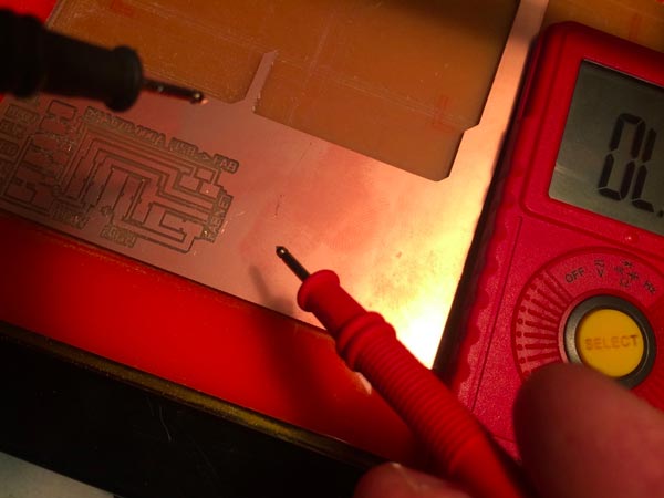
Casper produced and stuffed the Netfab board with the tutorial listed here: Before cutting the board out, he used the multimeter to check the traces:
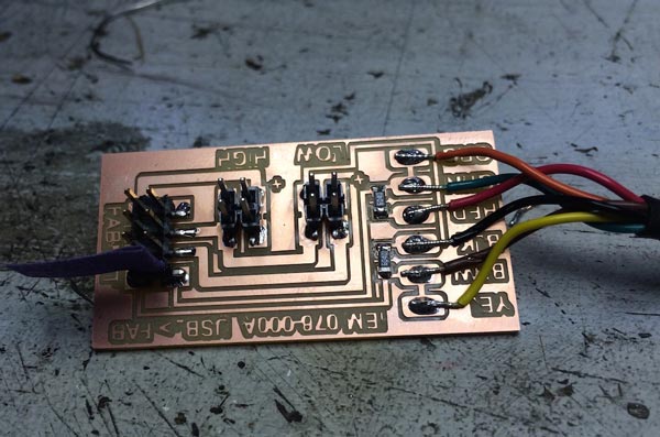
Natalia and Loes figured out the wiring of the netfab based on this documentation:as well as this one
The fuss about the wires was that first of all, the ribbons used in the examples are not the same as ours (10-wire ribbon vs our 9-wire ribbon with colors in the different order). Different connectors available. And not all the pins of the header on the netfab need to be connected. So we had to figure out what goes where. We looked at the schematics and board layouts provided in the documentation and mapped out the wiring to translate it to what we have in our fablab. We documented what should go where without actually making the cables yet because the sizing of the machine isn’t clear yet. But actually making them will be a 5 min job once we know.
We prepared this and tested it separately, didn’t implement this into the entire system yet.
We decided to create end stops on the machine for safety, and got the supplies to build some switches into the machine so that when the end effector reaches the end of the stage, it will stop. We need two for each degree of freedom, so 8 in total.
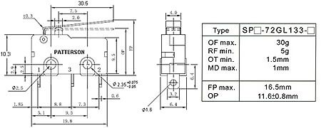
We got this velleman switch which we bought at Rotor.eu. Technical drawing can be found here
To get those to work accordingly we first wanted to design and and produce another node so that the switches can be connected to the network of the Gestalt nodes. We could do that with an ATMega328 as used on the Gestalt nodes. There’s an Arduino lib on the Github that supports this chip to work with the RS-485 protocol. We looked into it, and figured out how to work with the clock (see § below) and change things in the library to make it work with a 20mHz resonator instead of the recommended 16 or 18.4mHz (which we don’t have), but then decided against it.
Resonator for clock: 16, 18.4 or 20 mHz?
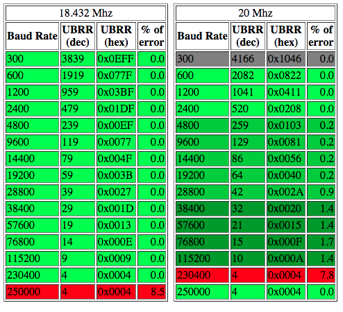
We don’t have a 16mHz (recommended for ATMega328) or 18.4mHz (used in Gestalt Nodes) clock. The nearest is a 20mHz clock. We looked at the Arduino library written for gestalt (the .cpp in the github file. We calculated what the USBRR0 value should be at a 20MhZ clock to run baudrate of 76800 BPS (which according to annotation in the code works more smoothly than 115300 when tested). We will add another if loop in the lib, that looks for if USBRR0 = 15 as this conversion table shows
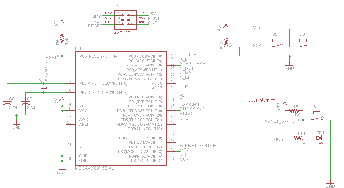
Then Zaerc had a clever suggestion: check in the schematic of the Gestalt nodes if you can repurpose the ISP headers as lines to the end switches. And BINGO! The MISO and SCK pins of the ISP header are only connected to the IC, so once the nodes are programmed, you can hook them up to something else and use thesame pins as an input (eg to measure whether your end effector has reached its limits :). Initially we put it on MISO and MOSI but MOSI has an LED and resistor attached to it, so SCK is better (ignore mistakes in pics below).
Use Switches as NC (marked on component). Normally Closed closes the circuit when the button is not being pressed. So it will send signals all the time, UNLESS you press the switch (end effector reaches the end). That way you protect the system. If you’re machine breaks, eg. iif a cable breaks and makes a faulty connection the machine will also stop. If you do it the other way, you break a cable, the machine will push through the end because it doesn’t get a signal to stop anymore.
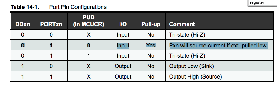
ATMega has internal pull-up resistors built into the chip. We need to enable them in the C-code by making sure the register of the MISO pin (PB3/PCINT3/pin15) and MISO pin (PB4/PCINT4/pin16) (DDRB, PORTB, PINB etc etc) are enabled as INPUTS, and make sure that the pullup resister is enabled. See table 14-1 in the ATMega328P datasheet:
This is the C code so far (needs to be implemented):
End Switch CodeAfter testing hot wire cutting, Till sat together with Natalia and Casper. They worked on hooking up the Gestalt nodes. First they read and followed these two tutorials:
Natalia and Till made an appropriate cable to connect the Fabnet USB and the first Gestalt nodes. This had to be carefully done. After figuring out how to connect a FabTiny*ISP to a Gestalt nodes, Till ran a Terminal test command in order to make a basic check and initialize the Gestalt nodes: avrdude -c usbtiny -p m328p. It worked well.
They all downloaded the Gestalt Single Stepper Node. To install the firmware on each node, Till located the right folder in the Terminal and ran the Makefile. He tripped on an error message and had to edit the Makefile in order to indicate my FabTiny*ISP. He replaced avrisp2 w/ usbtiny and saved it. He ran the make command followed by make program-usbtiny-fuses. Till successfully installed the firmware on the first node. Natalia and Casper repeated these steps and installed the firmware on the other 3 Gestalt nodes. Thanks to Zaerc for giving some advice!
Please download the saved Terminal output here.
Next, they downloaded and installed the Gestalt framework and followed the tutorial Getting Started With Gestalt Nodes to set up and test the environment.
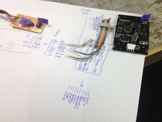
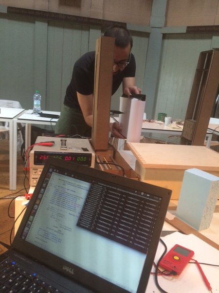
Again, they tripped on some error messages. They double-checked the connections using a multimeter and reviewing schematics. The photo below shows our setup. It differed from the tutorial by James.
They tried to connect 2 nodes and ran some of the sample code, but they got another error message in the Terminal. The serial communication seemed to not properly work. They had to edit the script and determine the FDTI serial interface. They stopped here. It was already evening and they decided to go on with it the next day.
Till, Natalia and Casper worked on hooking up the Gestalt nodes. They read and followed these two tutorials:
First they made an appropriate cable to connect the Fabnet USB and the first Gestalt node. This had to be carefully done. After figuring out how to connect a FabTiny*ISP to a Gestalt node, Till ran a Terminal test command avrdude -c usbtiny -p m328p in order to make a basic check and initialize the Gestalt nodes. They all downloaded the Gestalt Single Stepper Node. To install the firmware on each node, Till located the right folder in Terminal and ran the Makefile. He tripped on an error message and had to edit the Makefile in order to indicating his FabTiny*ISP. He replaced avrisp2 w/ usbtiny and saved it. He ran the make command and then the make program-usbtiny-fuses. Till successfully installed the firmware on the first node. Natalia and Casper repeated these steps and installed the firmware on the other 3 Gestalt nodes. Thanks to Zaerc for giving advice!
Next, they downloaded and installed the Gestalt framework and followed the tutorial Getting Started With Gestalt Nodes to set up and test the environment. Again, they tripped on some error messages.
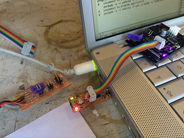
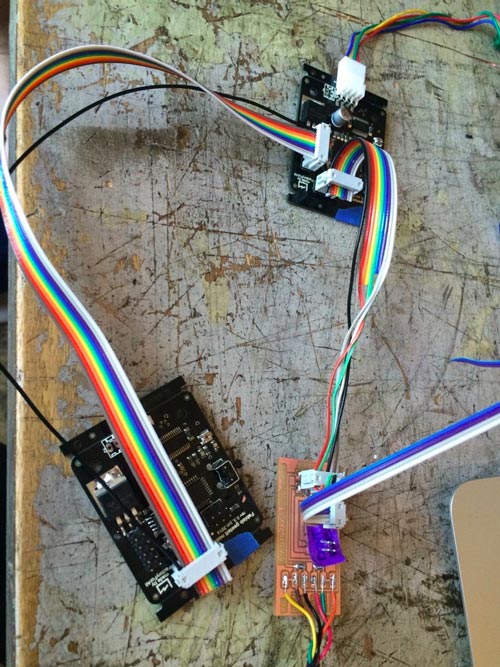
When they connected the nodes, they used a multimeter and the schematics to check that all cables were connected right to the nodes’ pins. Please see the photo. This looked a bit different from what is shown on that tutorial by James.
We then tried to connect 2 nodes and run some of the sample code, but we got an error message in the Terminal:
File "xynode.py", line 7, in
from gestalt import nodes
ImportError: cannot import name nodes
At this point, it was the end of the day, so would look at this the next day. Probably we had to give each node a unique address when installing the firmware?
The next day, it seemed that the import error was because we all tried to import the .py code using a Mac. Using a Mac, there was a conflict in the code because Gestalt import is also used for the OSX internal Gestalt library. Nadya provided a renamed version and nodes were able to be imported this time on github
//Important note, pyserial (version 2.7!) was not installed on my computer (Natalia) and at the first time the code failed. After the pyserial was installed there were no more installation glitches. check it here. When you do this if you get the following error:
import serial
#for connecting to serial ports
ImportError: No module named serial
Attempt to load the file single_node.py into 1 node had the following result:
ssds-MacBook-Pro:htmaa natalia$ python single_node.py
single_node.py: Warning: setting persistence without providing a name to the virtual machine can result in a conflict in multi-machine persistence files.
The second time I run the attempt the node didn’t even try to identify itself: Retrospect observation: that is probably because the test.vmp file exists! Delete it to reset attempts :P
The third time I run the attempt with a different node:
ssds-MacBook-Pro:htmaa natalia$ python single_node.py
single_node.py: Warning: setting persistence without providing a name to the virtual machine can result in a conflict in multi-machine persistence files
FABNET: port /dev/tty.usbserial-FTXW4F9H connected succesfully.
X Axis: Could not reach virtual node. Retrying (#2)
etc etc
X Axis: NO URL RECEIVED
X Axis: False
2 hours later, a small step to move the node: We’ve been running the code from the terminal, not having noticed that the hex file is in comments! steps to follow:
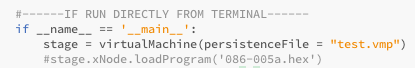
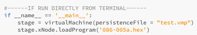
It works! code to send it to the end of the stage. Note the minus; is actually moving forward!

for every bracket of supercoords the machine changes direction! supercoords = [[20],[10]] //that will actually make 2 moves in opposite directions //false assumption, that didn’t happen at the 2nd day of trials. But the x needs a minus [-] in order to move forward, whereas the y doesn’t!
We decided our next steps would be to first get the axes moving one by one. After some research on what examples were already available, we found an example of a foamcutter in the pygestalt repositpory (examples --> machines → stages). Again, some parts of the program that were needed to run it successfully were in comments. We uncommented line 33 and 34:
and line 79 and 80:
And changed the path to the hex file:
and put the hex file in the same folder as the program.
There were a few examples in the foamcutter.py program. Some of them open a .csv file (comma separated values) while examples put the coordinates in the code directly. The coordinates can then be printed, checked and converted to movements of the gestalt nodes. It would be nice to have the program read coordinates from an external .csv file, so you can just change the .csv file and in stead of rewriting the python program. We first started by using coordinates in the code directly, so see how the coordinates relate to the gestalt nodes. We started of with testing one stage and a set of coordinates. We got one stage moving. Somehow, it a negative number moves it up, instead of down. For the second stage we attached, this wasn't the case.
After this was working and we could control two of the stages from coordinates in the code, we made the program read an external csv file with the same coordinates. And that worked.
Then we decided to hook up the two other stages and get them in the loop as well. At first, we couldn't identify the last gestalt node. This was the one we reprogrammed to test our endstops and apperently didn't put the right program back in place. We reprogrammed the original firmware and then it worked. Now we can control all the four stages with coordinates from an external .csv file. It can make a square. Here is the machine taking it’s first steps! We messed around with the velocity settings, but could figure it out.
Shirley assembled a cutting bed from scrap wood and foam at 17cm hight (Z-axis zero), then quickly set out to document everyones process on the go so that would also be finished by 3PM.
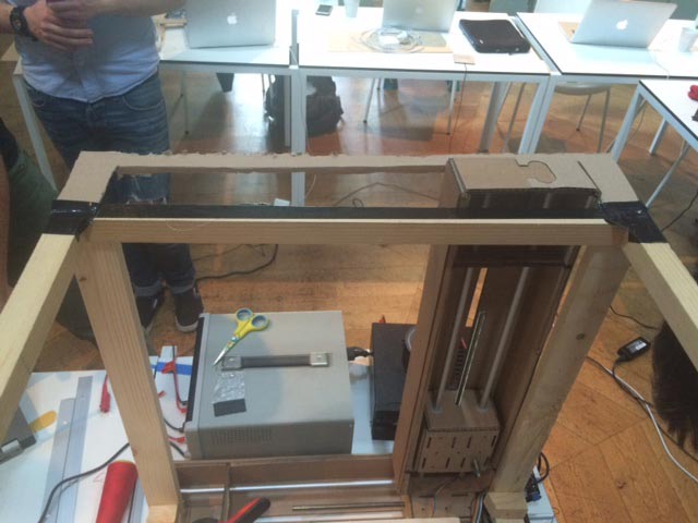
Casper, Till and Henk set out to make a housing from scrap wood that will guide the standing stages while moving, and fix the bottom stages to they won’t move. Do note the special guidance material Casper is proudly pointing out.
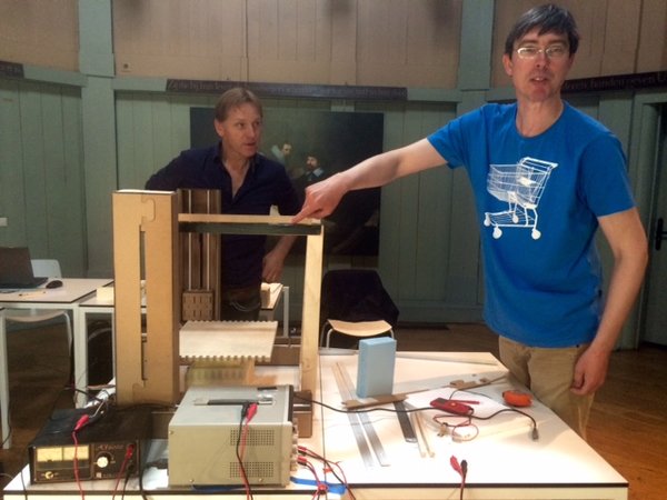
Casper, Henk and I worked on a guide system for the stages. Casper got a concept, so, Henk and Till helped him building an improvised construction from scratch.
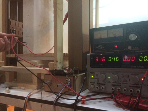
They got a big piece of foam differing from the foam which they previously used for a test cut. So, Till made another cutting test. They needed a second power supply which Till borrowed from the fab lab’s electronics workshop. He carefully set up a test environment. The wire wasn’t tightly clamped and he had to fix the 3D-printed wire mounting with some hot glue. Due to its age, the power supply got some idiosyncrasies. So, he tested it with a multimeter to be sure it would display the right value. Henk and Till determined that they need 2A and 7V to heat up the wire and cut the foam.
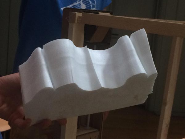
Later, when we computer-controlled cut our first piece, Till increased the power to more than 3A. The whole machine was unsteady but successfully cut a nice coded shape.
It turned out that the upright stages were not straight and slightly moving while cutting, so Joe and Shirley each made a “guidance system” for a stage, to see which would work better.
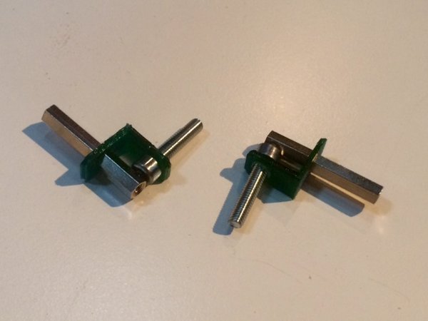
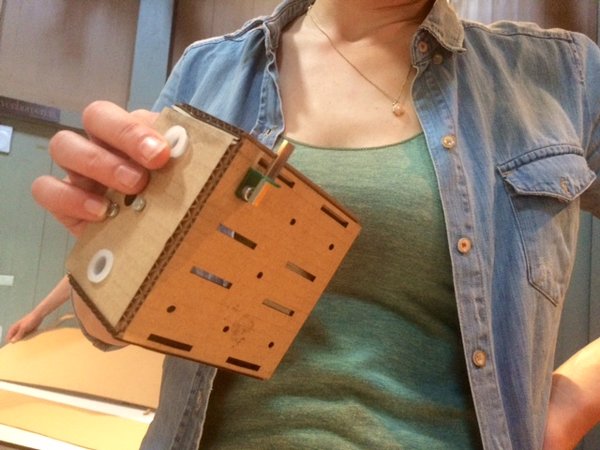
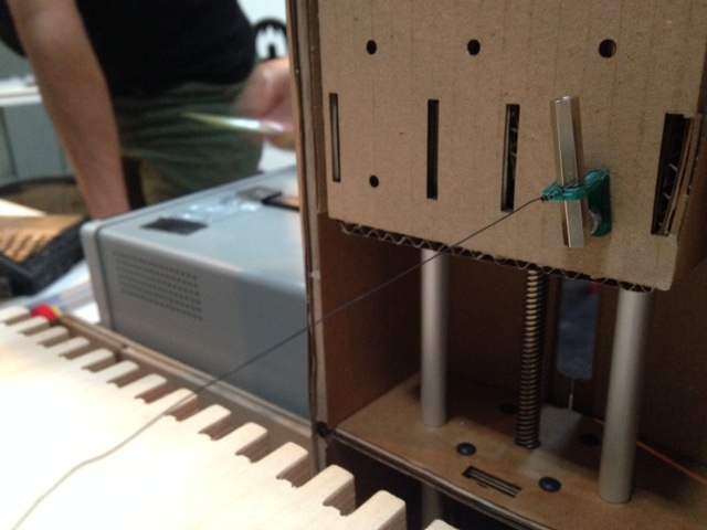
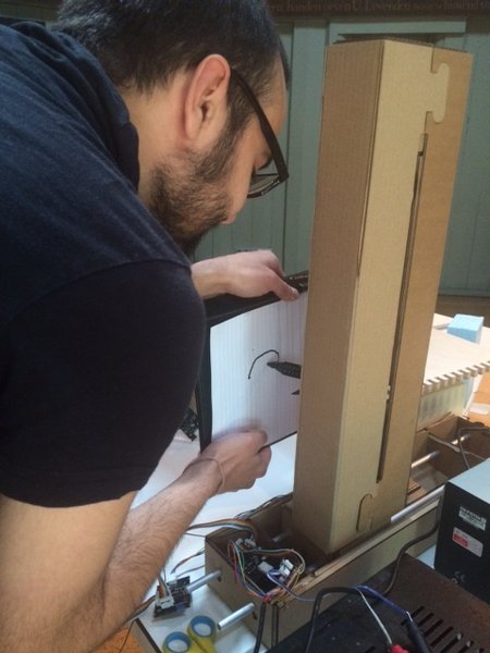
Loes and Joe set out to design and print the end effector - a non-conducting PLA part that will hold the hot wire and attach it to the moving part of the stage while avoiding any touching between the hot wire and the cardboard directly Cardboard would burn instantly, whereas the PLA can take the 100 degree celcius hot wire heat without melting. The sizing is a bit off. Could be improved by spacing the wires a bit further away from each others by making the PLA bit thicker but, this is the idea and it works. We hotglued it to the cardboard to keep it from turning. Two screws in the PLA part would be more elegant. The long hexagonal nut & bolt combo is an easy way to fasten the hot wire. You just wrap it around the bolt and screw the nut onto it.
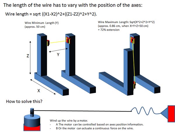
We already figured out how to let the python program read coordinates from a csv file. On each line of this file is a set of coordinates. Each set coordinate consists of four values, one for each stage/axis. During the test set up, we let the four stages to follow the shape of a square. This meant that the two pairs of stages make the same movement simultaneously. We could easily let the two pairs of stages do a different motion, but we haven’t yet made a flexible wire. Moving the two pairs non-simultaneously could break the wire when the left end effector moves too far from the right end effector.
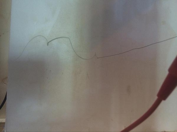
To be able to prove we can cut foam with four degrees of freedom, we had to made a toolpath that did not keep the left and right end effectors in the same position, but would keep the left and right end effector at the same distance of each other at all times. This was done by a sequence of motions, moving one end effector at a time. The path is based on half circles: while one of the end effectors is kept in one position (the center of the circle), the other end effector draws a half circle around this center. The end of the half circle is the center of the next half circle.
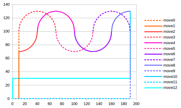
In the graph above, the dashed line is the right end effector and the continuous line is the left end effector.
This path was calculated by using mathematical formulas in a LibreOffice Calc document. It was done step move by move. The formula used to calculate the (half) circles is:
SQRT(POWER(C2,2)-POWER((A2-C2),2))
C2 is the center of the circle, A2 is the position on the X-axis and the outcome of this formula is the position on the Y-axis. After calculating the path with the half circles, it is saved as a csv file and copied to the directory of the python program that operates the machine. Then the name of this file is written in the program that operates the machine. This is the csv file we cut with the machine:
On Friday, Till and Koen met and spoke about some final tasks which had to be done. We still needed a stable bed, a stage guide as well as a properly clamped wire. Till decided to build a bed based on a simple cardboard construction. Till would design and cut the construction, Keon would design and fabricate a guide system as well as a system to tense the wire. They took some measurements of the machine. Then Till started to design.
The laser cutter was able to maximally machine a size of 46 × 96 cm. To keep it cheap and simple, he designed a bed based on small box elements made of laser-cut cardboard. Four sticks would support the stage guide. He found a long wooden stick in the workshop. It wasn’t long enough to make four pieces, so, he looked for a substitute and found a copper pipe. The wire’s tension would keep everything together. To laser-cut cardboard, he drew on Joe’s settings.
Unfortunately, Till wrote down a wrong value. Koen told him a number of 57 but he noted 75. He already cut the first cardboard sheets which they just bought. He didn't want to waste material and decided to go on and use the boxes already fabricated. Finally, He adjusted his design.
Design files
Color keys
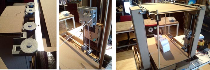
Production photos
The boxes were glued upon a cardboard sheet (36 × 57 cm) and covered with a surface cardboard sheet of the same size. Four 65 cm high sticks were plugged into the boxes and got a stable footing. The sticks supported two guides and a ceiling.
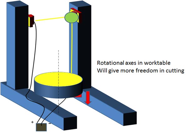
Concepts included:
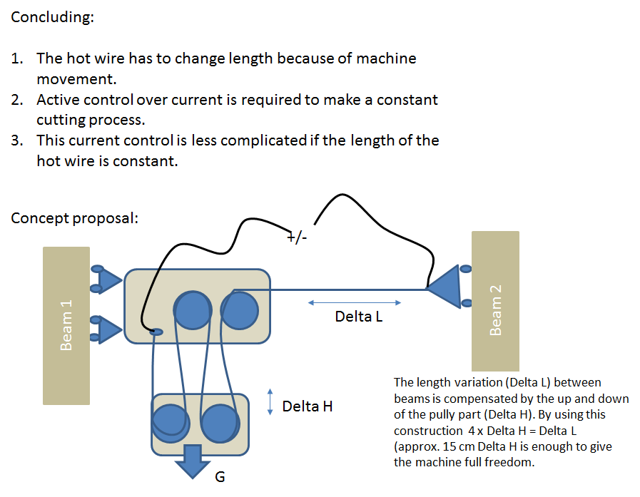
The concept is created by 3D printing. Left picture: A guide is created for the top part of the machine. I think this could work. Middle picture: a pully system is created for tensioning the hot wire and controlling the current.
Possible solutions
How important is the width of the machine?