Final Project
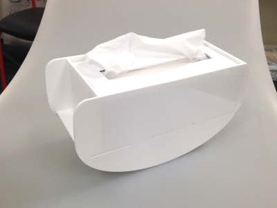
Sneezing Tissue Box
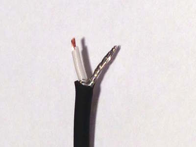
All of the materials used in this project are listed here.In this final project, my aim is to detect a sneeze (or loud noise) and make the tissue box move as it were sneezing itself. In this system I use a condenser microphone to detect sound and servo motors to make the tissue box move.
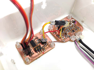
Making the microcontroller boards
Software: Eagle(7.2.0) for designing the PCBs, Gimp(2.8) for editing the png filesMachine: MODELA MDX-20 (Software: Fab modules)
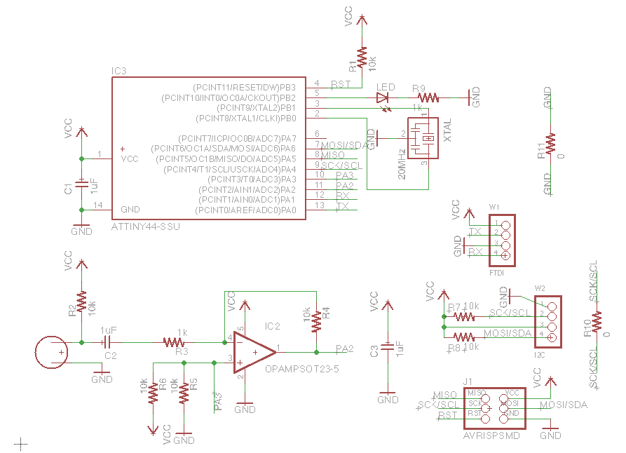
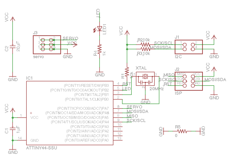
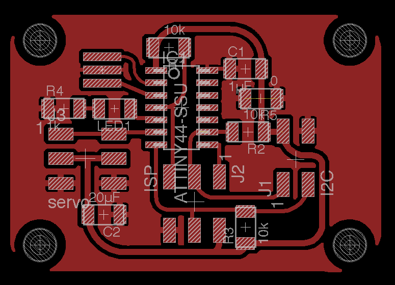
I want to be able to expand the system by connecting additional components (even after this Fab Academy ends), so I decided to use I2C communication between the microcontroller boards with Attiny 44s. The mic board is the master and the servo motor board is the slave. 4 wires are necessary to connect the boards: one to send data (SDA), one to share the clock (SCL), one for GND and one for VCC.
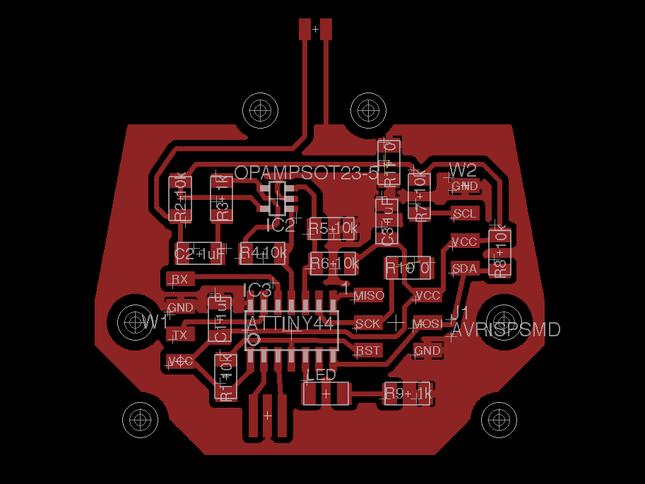
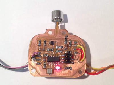
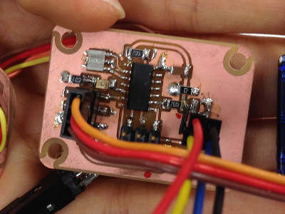
I designed the boards using Eagle. (I explain how to use Eagle and export png files in week 6) In the Board design, I made a GND plane. I also drew holes (3.2mm in diameter) so that the bards can be attached to the tissue box case with screws. I changed the tool diameter setting in Fab Modules from 0.4 to 0.3 (in order to mill all of the narrow traces) and begin milling the boards with the Modela. After the milling was done I checked the board for shorts with a tester, and then soldered the components.
Programming the boards
I changed Neil’s programs (c file, make file) for my Attiny44 board (c file, make file) and ran the python program to check that the mic was working. I also flashed the servo board (c file, make file) and made sure that two servo motors moved.For I2C communication I used the TinyWire library on Arduino (TinyWireM.zip, TinyWireS). In order to use the TinyWireM library I added the following code to USI_TWI_Master.h.
#if defined(__AVR_ATtiny84__) | \
defined(__AVR_ATtiny44__)
# define DDR_USI DDRA
# define PORT_USI PORTA
# define PIN_USI PINA
# define PORT_USI_SDA PORTA6
# define PORT_USI_SCL PORTA4
# define PIN_USI_SDA PINA6
# define PIN_USI_SCL PINA4
# define USI_START_COND_INT USISIF
# define USI_START_VECTOR USI_START_vect
# define USI_OVERFLOW_VECTOR USI_OVF_vect
#endif
The master program reads the mic signals. I set a threshold for the sound so that the master will send a signal to the slave whenever it detects loud noises. The slave will move the servos when it receives the signal from the master.
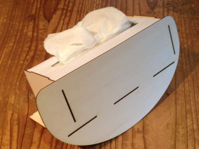
Making the tissue box case
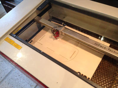
Software: Inkscape (0.91)Machine: Trotec Speedy100R
Settings: 5mm Cardboard: Raster Speed 3%, Power 20%, Vector Speed 1%, Power 40%
2mm Linden board: Vector Speed 0.9%, Power 60%
3mm Acrylic board: Vector Speed 0.9%, Power 85%
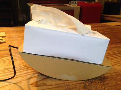
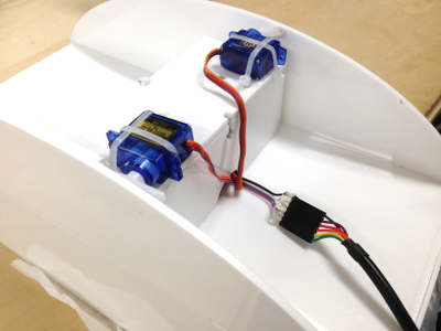
First, I designed the shape of the base of the tissue case and made a prototype by cutting cardboard with the laser cutter. I also attached servos at the bottom to see how it will move. I decided not to place the tissue box in the center, but shift it to one side to increase momentum of the rocking movement. After I figured out where to attach the servos, I designed the hole case and cut Linden board to check the measurements of the design. At last, I cut an acrylic board and assembled the pieces to make the final product. The circuit boards are attached to the case using screws and the servos are secured at the bottom of the case using cable ties.
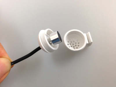
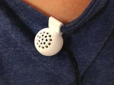
Making the microphone case
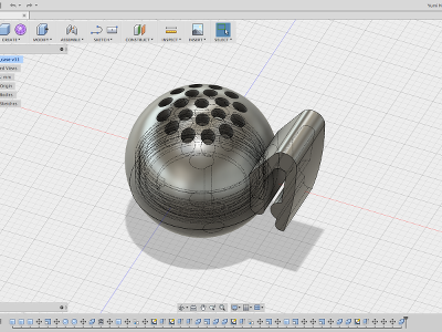
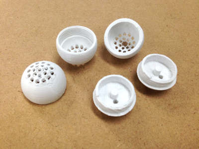
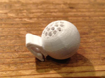
Software: Fusion 360Machine: Makerbot Replicator 2, PLA filament
Initially I was planning to make a case for the whole microphone board, but the size of the board ended up to be larger than I expected, and since I wanted to attach the mic as close to the persons face by clipping it to his/her shirt and I wanted to make it as compact as possible, I decided to encapsulate only the condensor mic. I modelled the case using Fusion 360 in a way that bottom part and top part can be screwed together. With the 3D printer I repeated the process of printing and adjusting the data about 4 times until the two parts fit together. Then I added the clip part to the case’s data and printed the final version. (Modelling process can be viewed here. The 3D data can be viewed and download here.)
Links
