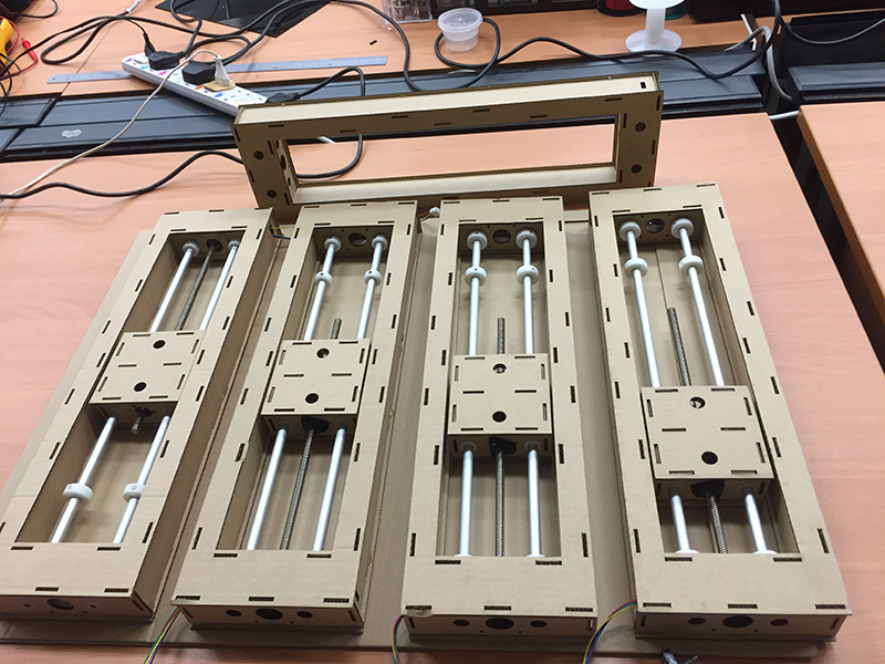
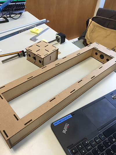
For Machine Design Week. The group decided to build a 4 modular stages which would cut foam.I lead the team in the Mechanical Design and divided the tasks amongst Walter and Edward. The 3 of us took care of the Design, Fabrication and Assembly of the machine. Rodney and Steven took care of the electronics. The material used was cardboard and some of the components were 3D printed.
The 3D files and .pdf files for laser cutting can be downloaded from
https://www.dropbox.com/sh/cgq94imwod59a5r/AAAQPiDu6sc-V6o_KbKvbH8la?dl=0
or
The stock cardboard that we have had some camber, so there were some challenges in cutting the default designs provided by Nadya. The camber made it difficult to do half cuts. We did our own snap fit design in a day and went to the Epilog to get the pieces out. In comparison, I think Nadya's design has more rigidity as it is folded and glued. I will try Nadya's design when we get our hands on flatter boards. Nevertheless I like the clean Muji Design like look of our stages.
I really like the concept of modular stages as it allows various configuration to build different kinds of machines. These provides a wide range of flexibility and possibilities. This website is really cool.
http://mtm.cba.mit.edu/machines/science/
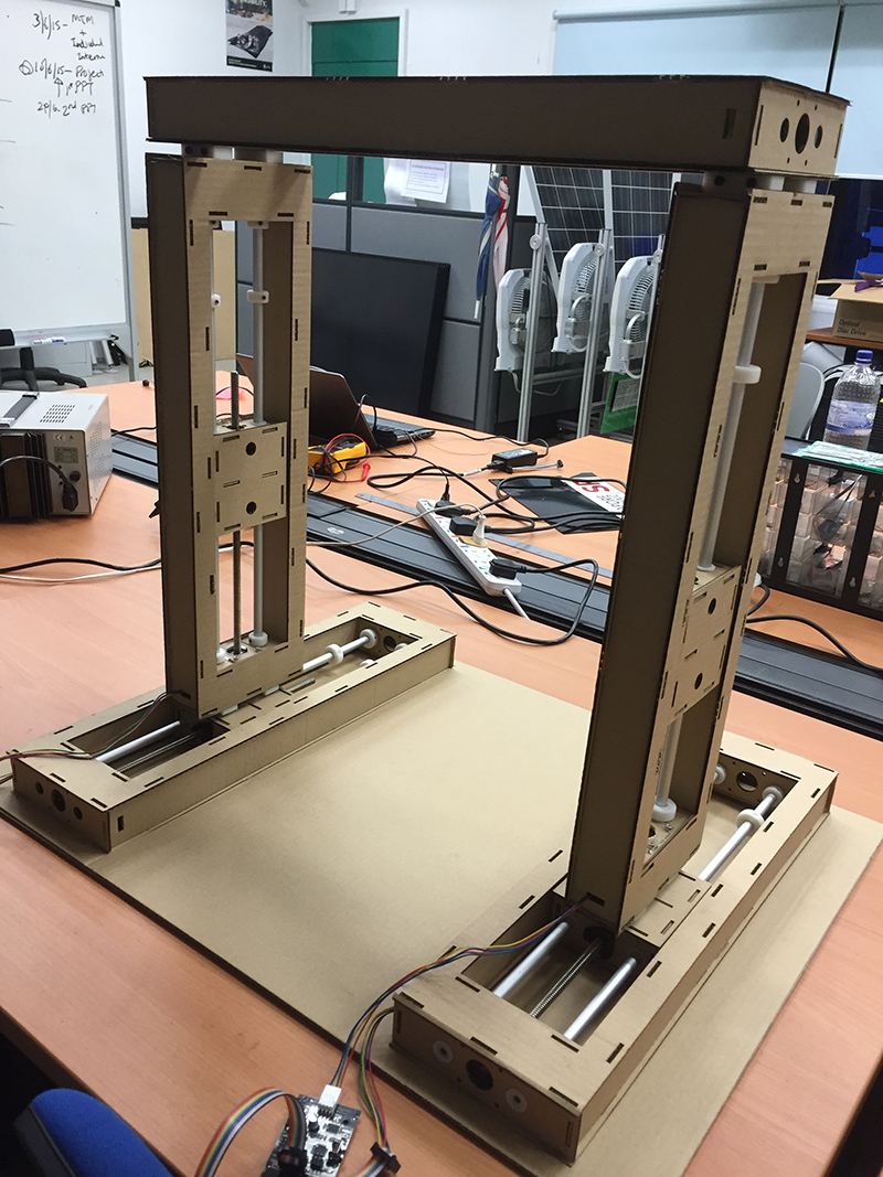
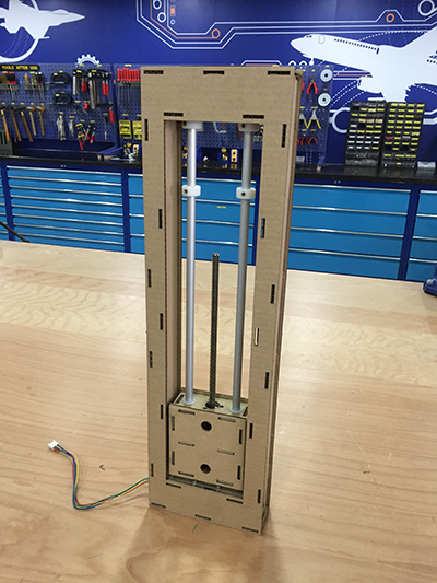
My Individual contribution in this Machine Building Assignment is in leading the mechanical design and fabrication of the cardboard structures. The team brainstormed and from the sketches, we decided on a modular system to develop. I took the lead in the equal distribution of task in the mechanical design. I designed the outer "O" section, Walter designed the "saddle" the centre movable segment. and Edward designed and fabricated the attachment blocks and nichrome wire attachments. The integration of all the CAD design was done by me, and i checked for interferences both dynamic and static. The mechanical build assembly was done by Walter, Edward and Myself. Testing done before the systme was handed over to Steven and Rodney to carry out the programming. There was some structural instability after the assembly, but that was resolved through the design of side brackets that braced the modules.
The design is modular in nature and can be fitted in a wide array of configurations. The centre top bridge as as a stablizer between the axis, so that the tension of the wire would not pull the towers inward.
Collars were designed and 3D printed out. These little fellows acted as hardstops for the the saddle and Aluminium slide shafts. Future systems would have limit switches incorporated into it.
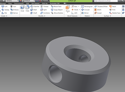
The collar went through 2 design iterations. The collar has a PEM M3 insert for a grub screw. However due to the soft ABS 3D printed part, the PEM insert could be easily pushed out as the screw is tighted. Hence the design is changed to ensure that this does not happen by having the insert pressed from the opposite direction.