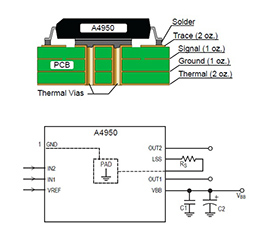
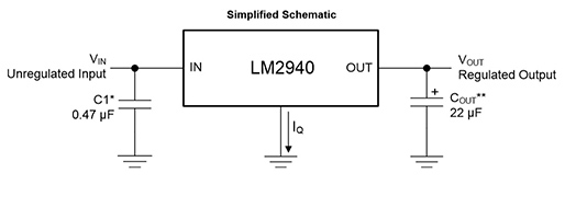
| The assignment for this week is to work on one output device. I have selected to run a DC motor as I need it to spin my astromech's head. So taking reference to Neils layout, I designed a similar layout to test it out. I had to go through the data spec sheet to ensure that the pin layout is the same as the A4953 as I was using its cousin A4950. Next was the 5V voltage regulator. I was deciding on the baby one that Niel has or the beefy version. So I went back to the spec sheet to make sure that it was compatible. | ||
|
|
|
| H-Bridge pin layout | 5V regulator schematic | |
 |
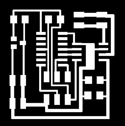 |
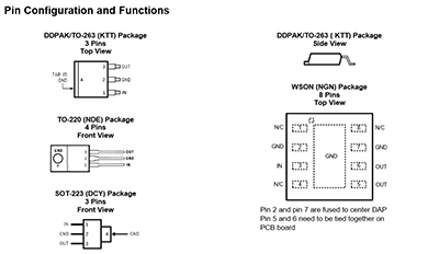
| The various pin configs of the LM2940 | H-bridge board traces |
.JPG) |
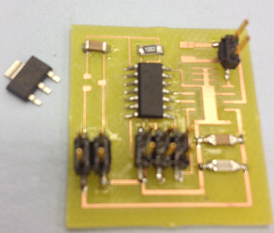 |
| H-bridge Board | Can't use the big Reg |
The eagle CAD files can be downloaded from the file https://www.dropbox.com/sh/hns4c9d98gkh48n/AADQ85v_EHMCTe52bmF6L68Ha?dl=0 or I cut the board on the LPKF dedicated PCM milling machine as I had some troubles with getting my little backyard router to work with the Fabmodules. I stuffed the board and fired it up and I think I killed the baby 5V regulator. ( I used it cos it was available) only to realize that I got the in and out pins wrong. I could not use the bigger regulator cos the pad layout was wrong. I also tried using the fabmodules and milled the motor driver on a smaller machine.you can download the .nc files from https://www.dropbox.com/sh/05kw4yvvc1vn66k/AACe4N9gUfdR5IioTLFpKJSya?dl=0 or I was desparate to get this board up and running so I hacked it and put a lovely Giant Grand Daddy 5V reg on my board. I know Neil would frown...but i wanted to see the motor spin NOW!!!! |
|
 |
|
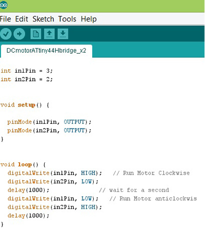
| The LM7805 | sketch from the IDE |
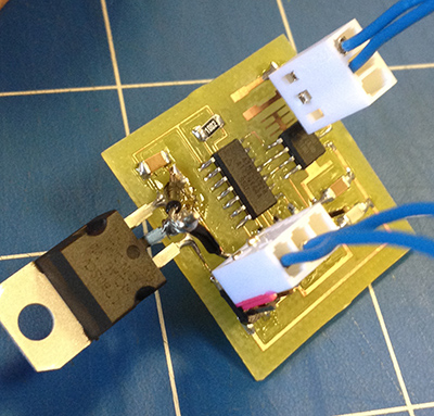
So I tried to salvage the situation and found this huge 5V reg. I checked the specsheet and it seems ok to run so I did a massive invasive surgury on my board. It is ugly I know...but it works :) |
|
The code can be downloaded from https://www.dropbox.com/s/ujc8lhxqu0rso2h/DCmotorATtiny44Hbridge_x2.ino?dl=0 or
|
|