ELECTRONICS DESIGN

This is my first time working on eagle cad. I learnt a fair bit from this site.

http://academy.cba.mit.edu/content/tutorials/akf/electronics_design_eagle.html

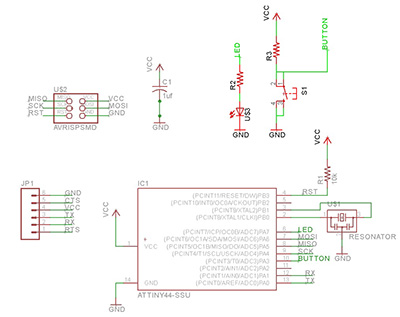
Below is the schematic that I modified. I added in the push button and LED. That was enough to keep me busy with Eagle CAD.

Eagle CAD was quite intuitive. I got the hang of it right away. What I like too are the libraries that the FABlab created. That makes it a whole lot easier in selecting the components that we need for this assignment.

Schematic Board layout
To add components, I needed to add the libraries to have access to the components. The rest of the design process is illustrated as follows:
Add Components Select the one you want and drop DRC-Rules
Specify the width, click on check Trouble spots shown Make Gerber Files


There is a need to specify your border in layer 20 so that the border gerber files can be created.

If you are using the web based FabModules, export image and select 500dpi. it is in a .png format.


Open a Job Process Job  

Next is to mill out the boards and solder the components. And that would be this week's assignment.

https://www.dropbox.com/sh/92uzcacmz5tqnji/AAC0p1I4grL43740lgkdGYCIa?dl=0

or

local archive

We realized that we do not have the resonator. so for now we will probably have to depend on the internal clock to run this chip.After stuffing the board we are ready for next week's lesson on Embedded Programming. Looking forward to some interesting coding :)