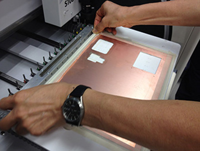
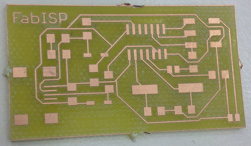
We used a single layer board and pasted it on the bed with masking tape.
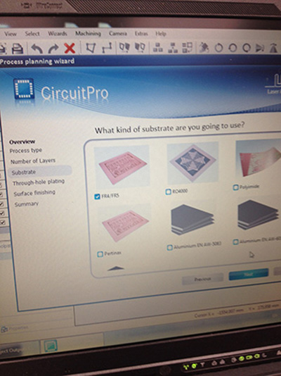
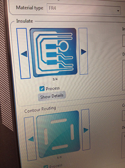
Subsequently the driver / UI guided us through from the loading of the gerber files and tool selection. There was a fair bit of selections and parameter settings that was required before the job actually started.
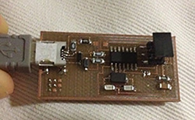
The components came :) and I did some practice on damaged boards. Walter was my teacher :) Thanks Walter!
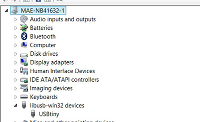
The toughest to solder was the USB connector. I tested for connectivity after soldering each component, because I was not too sure of my skill. After the board was filled, we hooked it up to my computer and I spent some time figuring out how to program it. After lots of help from Steven, my board is alive. I look forward to spawning more ATiny44 in the weeks to come. The tiny44 is unique unlike the UNO, I needed to find a driver for it and when I finally did, it showed up nice and happy on my device manager. It has its own unique usb protocol and does not have a serial com port assigned to it. (an interesting fact learnt over this weekend)
In this next session, I will discuss in detail how I use the Fabmodules to generate the .nc file and use a cheaper router to mill out a PCB.
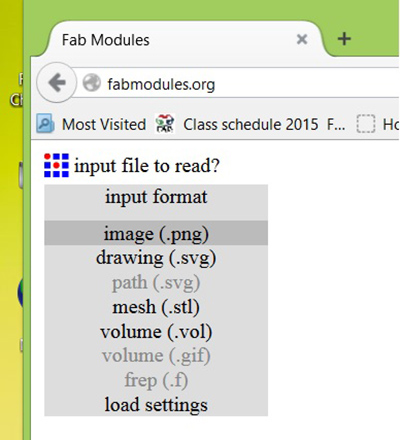
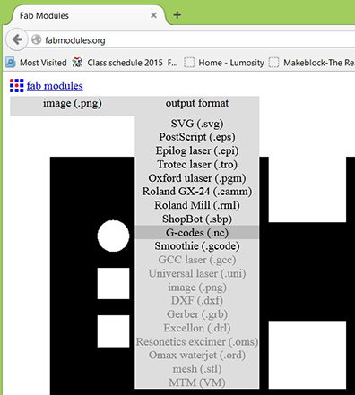
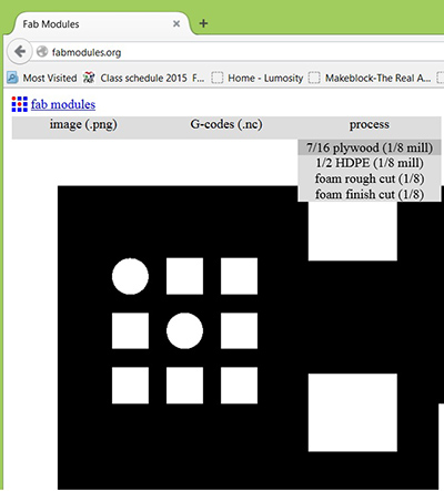
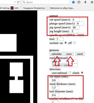
First you would need to have a .png file of the circuit in black and white contrast. using the webbrowser (Mozilla FireFox) go to http://fabmodules.org/ . Follow the sequence as per the pictures below to get your desired .nc file
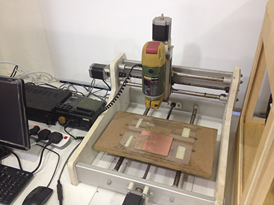
The following are the steps for starting the mill job.
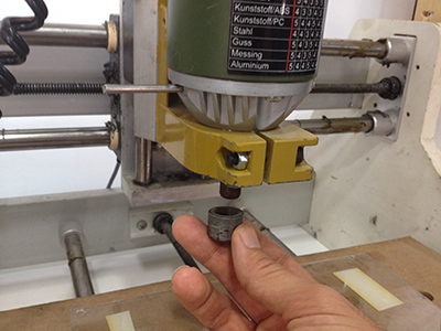
Step 1 : Set up the appropriate mill bit size. There is a need to insert the steel rod to lock the spindle. Remember to remove it before operation.
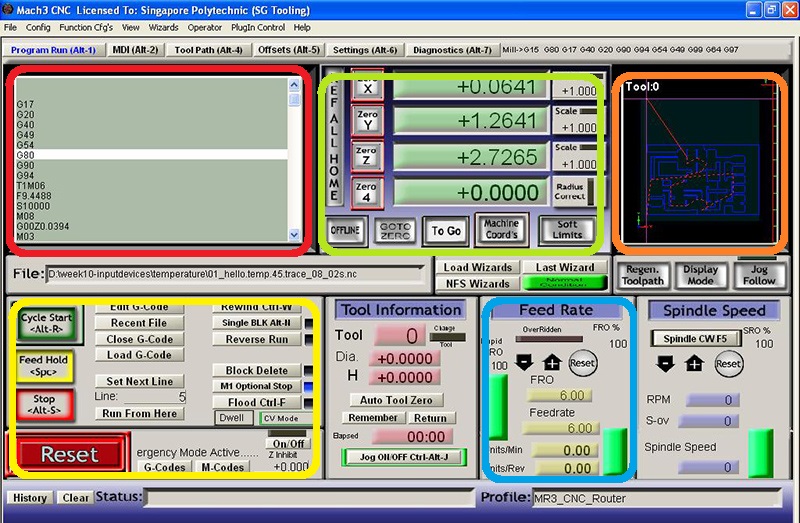
Step 2: load the .nc file, you can see it in the red box region. You can move the X,Y,Z of the router via the arrow key pads on the keyboard Spindle Z is controlled by Page Up and Page Down.
Step 3: Set the X, Y, Z to zero (in the Orange box region). Set Z zero a little higher to test the path of the new program before actual cutting. This would allow you to verify if the feed rate is ok. Feed rate can be adjusted in the Blue box region.
Step 4: Reset the Z height to the correct zero and you can Cycle start the program (YelloBox) you would need to press it several times to skip the G-code on tool change as this mini router does not have a tool change module.
Step 5: Wear safety goggles and stand behind screen. hand on the space bar for pause if anything goes wrong. The Orange box reflects the tool position and tool paths that are completed.
The fabmodules could also output files for Roland machines (.rml). The files can be found here
https://www.dropbox.com/s/un7sc9mj3y64gof/hello_ISP_44_traces.rml?dl=0
or