I am a Star Wars Fan, and I hope that through building an astromech, students may be inspired to do the same at the the FabLab. It would be a chance to show what the possibilities are.
I convinced my buddy Edward Tey who is also in this course, to build an astromech. I will build the head and he will build the body. It is a 1/2 scaled version, so the astromech is around 500mm tall. Let's hope it works :)
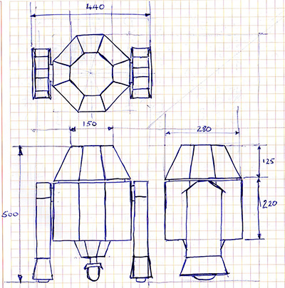
The architecture of the project could be broken down into 3 main systems. 1st the Mechanical Structure of the head. 2nd is the the drive mechanism system and lastly it is the Electronics system that is the brain of the entire project (without which it would barely make it as a worthless sculpture)
The technologies I would employ would most probably be a 2D router or laser cutter for the panels, 3D printing for some small parts, Standard mechanical components would be procured from a local robotics shop/hardware shop. I believe we would be using an Arduino controller to give it "intelligence" and to drive output devices. The following sketches reflect the design flow from my head to paper, before i transition to 3D CAD and detailed designing. - 1st Feb 2015
Detailed CAD Design
Overview of Sturcture
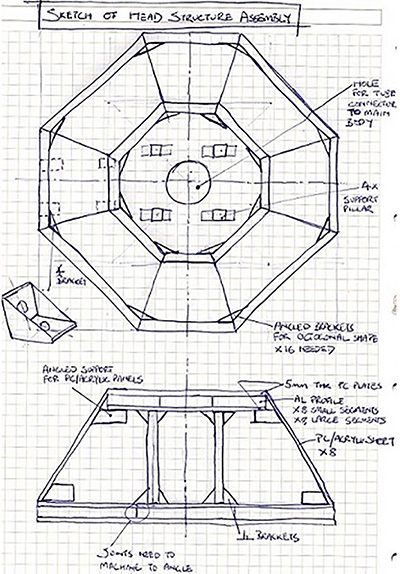
Design Taking the concept and translating into 3D CAD, I chose Autodesk Inventor as my weapon of choice. I approached designing the structure first. The structure is made of of 2 sub assemblies, the top and bottom plates. They are connected by 4 columns and the side panels would provide the necessary structural support too.
Bottom Plate Assembly
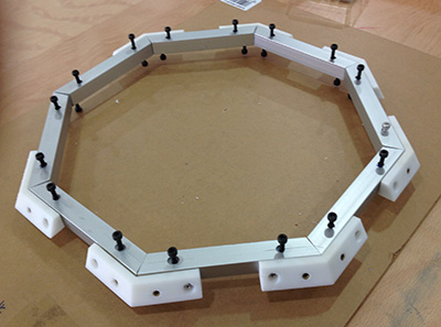
The bottom plate assembly consists of AL profile struts that are connected together by elbows.These elbows will be 3D printed. The octogon is then sandwiched by 2 Lexan PolyCarbonate plates. The outer elbows are also 3D printed, they provide the necessary surface to attach the outer panels at an angle. These outer elbows are secured to the Aluminium struts.

Top Plate Assembly
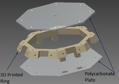
The top assembly, being a smaller octogon, I have done away with the Aluminium struts. It is going to be a 3D printed Octogonal ring and sandwiched between 2 PC plates.

Head Structure Assembly
The 2 Sub Assemblies and connected by 4 x Aluminium columns. The side panels would be attached and the structural assembly is complete. The Aluminium coloumns also act as a support structure for any future add on mechanisms.
After completing the design, it did dawn upon that I could adopt the apple mac book multi-body approach to the base design. Perhaps I will when I have all the sub-systems added in. As of now, I think this is good enough as it provides me the flexibility of adding new systems within the architecture.
As far as possible I try to design to whole numbers, but sometimes when angles come into play you cannot avoid running into the decimals.Inventor allows us to edit parts within the assembly, creating sketches and projecting edges from other parts. This saves me a whole lot of headache in the design.
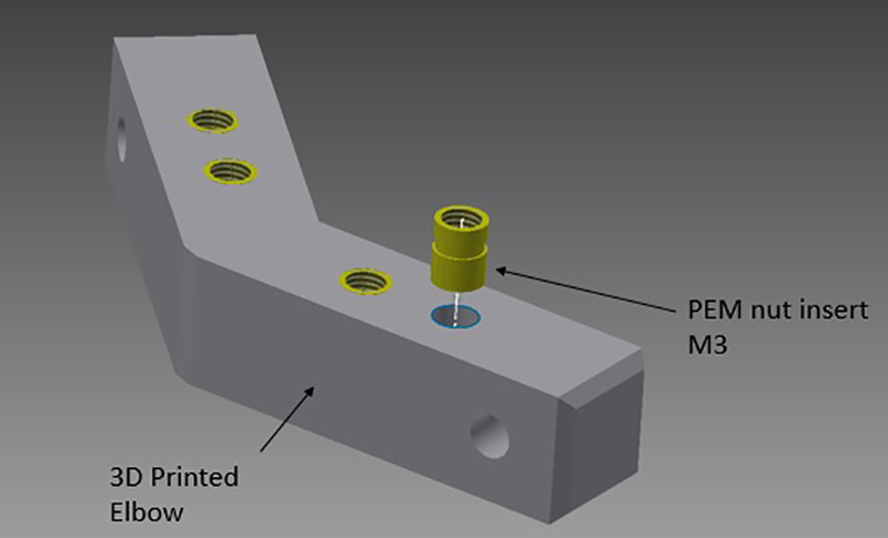
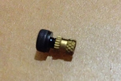
As for fasterners used, I would be using PEM nut inserts for M3 screws. These nuts are pressfit into plastic parts. Although the pull out force is questionable, but it beats threading on the plastics. And I know for sure that I would be dismantling it several times for sure the threads would strip if i tapped directly onto plastics.
Drive Mechanism Design
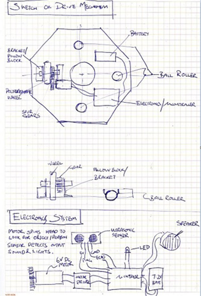
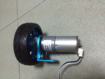
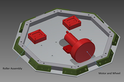
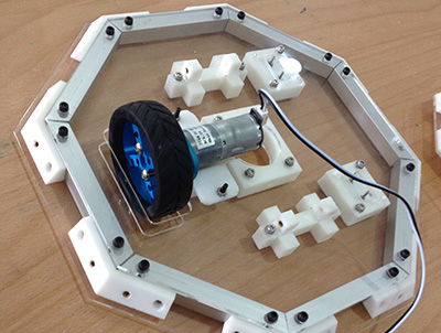
The Drive Mechanism system would be made up of 1 DC geared motor attached directly to a wheel and 2 x Ball rollers. These components would be mounted on the Bottom Base Assembly.
The components are all sourced from local robotic vendors.

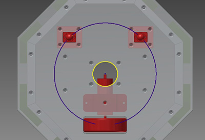
The position of these components all lie on a pitch centre diameter. The face width of the wheel is rather large and there may be unescessary losses as it is driven in circles. We will keep that in mind and watch for any problems from this area of concern.
The rollers are mounted on holders that are sandwiched between the 2 PC plates. Picture at bottom right has the top plate hidden for clarity.
All 3D files can be found in this link. I saved the entire assembly in .step format. So when you open it you would get the entire assembly including the individual part files.
https://www.dropbox.com/sh/y3c0qw8j4ckkhwh/AAC1rRBPxJawB1VjFsPhT2_Ia?dl=0
or
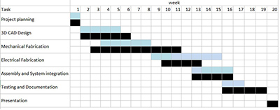
Project Schedule
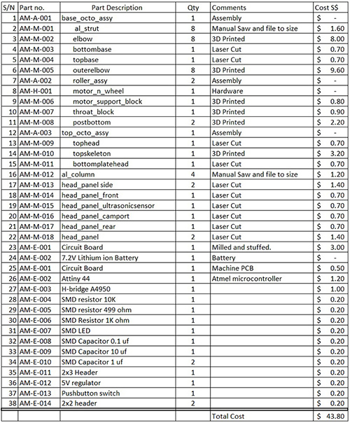
Bill of Materials (BOM)
Fabrication
Fabrication of Structure
The structure is made out of parts that employ the technologies of 3D printing(components) and Laser cutting(Sidepanels). I use PEM nuts to insert into the holes and this are perfect thread solutions as I know that there will be a fair bit of screwing and unscrewing. Pull out force is a concern especially with the soft ABS material that is not printing in full density. However that issue is resolved through geometrical design and the installation of the PEM is not as per manufacturer's recommendation.


Electronics Design
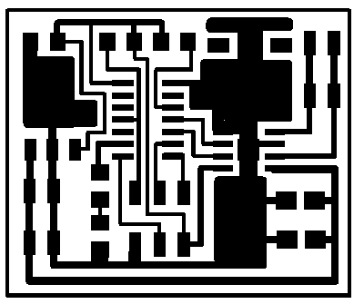
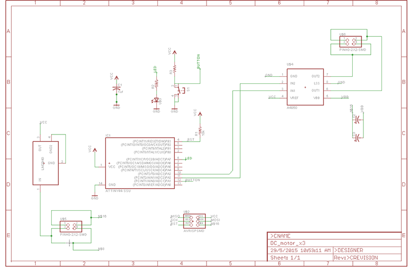
The Eagle files can be downloaded here
https://www.dropbox.com/sh/nerxohkw0avp6b6/AADALkriDDNwzylmsYcgvGXla?dl=0
or
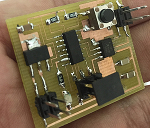
Finished stuffing the board.
Next is to test it!
Testing
The main objective of the Project is to have the head move upon the activation of an input device. It could be a push button or an ultrasonic sensor. The testing is done in stages leading to towards the final objective.
Test Plan A <Mechanical Assembly> To Assemble the entire Structure assembly and test for unobstructed motion physically by moving the Head Structure over the test rig.
Results - Movement was unobstructed, however the screw heads height of the screwheads at the bottom face were a concern. The gap between the head of the body is just over 3mm. Over the next few weeks I would order in low profile head screws
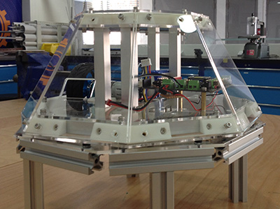
The Head Structure mounted on a Test Rig ready for Testing. The Test Rig simulates that body which my course mate would be developing.
Test Plan B < Mobility and DC motor>- To hook up the drive mechanism to a DC power supply or an arduino and drive the head clockwise and anti clockwise. This is to test the motor and the mobility of the head.
Results - This was done using a DFRobot All in one microcontroller that has 2x built in DC motor drivers and an Xbee chip setup. I ran the test wirelessly and the Head was able to run smoothly. At lower PWM, the motor was not able to drive the head. At higher PWM there was no problem, but the speed was a little too high. I could change the gear ratio to fix this.
Test Plan C < Test Microcontroller Board>- To test the functionality of the electronics and check for any bad connections.
Results:
1) The onboard LED did not respond to a normal blink program. after some investigations. I found out that the regulator was giving an output voltage of 6.3V and the Tiny44 did not respond well to that. After swapping it with a huge L7805CV it worked fine the LED blinked
2) The test was done on a 9V battery and the motor used was a small 6V DC not loaded. But the motor did not run. After a chat with my electrical friends, I found out that you are not suppose to use solder to conduct the heat away from the H-bridge. Hence I might have short circuited the chip. I took the chip out, soaked up the solder and put the H-bridge back. and everything worked well.

Results :
1) Initially when the power supply was set at 6V, the motor did not run even though the motor was rated 6V. With the help of Steven, and after checking the A4950 spec sheet, we found out that the chip requires a minimum VBB of 8V-40V.
2) At setting of 7.7V the head was able to rotate as programmed. With this Test Plan D completed, I have met my minium base objective, and will move on to add more features and functionality to the head following the philosophy of Spiral Development.
3) The code can be downloaded here
https://www.dropbox.com/sh/nerxohkw0avp6b6/AADALkriDDNwzylmsYcgvGXla?dl=0