- The Windows installation was the easiest.
- At first, I was not able to install EAGLE on the 64-bit Ubuntu system. I used the internet to search the problem and discovered that EAGLE 6.5.0 for Linux was only available in a 32-bit version. The frequently asked questions section at CadSoft (http://www.cadsoftusa.com/training/faq/) identified some additional dependency files that would need to be installed. After installing the dependency files I was able to install EAGLE, but I could not get it to give me the option to run it in Freeware mode.
- I then installed the 32-bit version of Ubuntu 12.04 on another desktop computer. I was able to install EAGLE in freeware mode onto this computer without any problems.
- In the beginning of Fab Academy I almost installed Ubuntu v13.10. Now after six weeks of experience installing and testing many different software packages on Ubuntu systems, I have concluded that the 32-bit version of Ubuntu v12.04 is most compatible version to use for Fab Lab related applications at this point this point in time.
- Download the latest version of fab.lbr file.
- Copy this file to the EAGLE-6.5.0/lbr/ directory.
- Then from EAGLE control console you can toggle on or off the use of selected component libraries. Find fab.lbr and make sure it is selected to be used (Library --> "Use..."). I think by default, every component library is selected for use. This can be a little overwhelming when looking for components. You may want to turn off all the libraries you don't want to use.
- According to the data sheet for our 160-1169-1-ND, Green Clear 1206 SMD LED:
DC Forward Current = 40 mA Forward Voltage VF = 1.8 V (2.4V max) IF = 20mA
Supply 5V, Voltage drop across LED 1.8V, Desired LED current 20mA = 160 ohm (nearest higher is 180 ohm) Supply 5V, Voltage drop across LED 1.8V, Desired LED current 40mA = 80 ohm (nearest higher is 82 ohm)
Supply 5V, Voltage drop across LED 1.8V, Desired LED current 6.4mA = 500 ohm
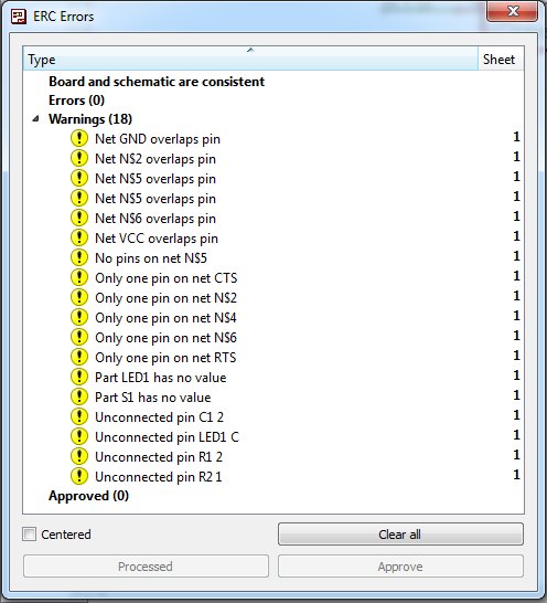
Results of the first Electrical Rules Check of my schematic
- I had over lapped several nets. Basically my net did not connect to end of component line but instead to some place towards the middle of the component. My nets overlapped the lines for the components. I thought it would automatically snap to the ends of the components.
- I also used two or more nets to connect components when doing 45 degree bends or routing around a component. The software apparently looks at each as separate wire and misses the connection to the component. You need to draw one continuous net between pins.

This is an example of two ERC errors caused by a single overlapping net connection.

Finished EAGLE schematic with pushbutton and LED added.

By default, none of the components were positioned on the board (the white outline in upper right corner).

Components moved onto the board. Notice all connections are shown as yellow lines that are the shorted path between the two points. These are called air wires.

After using the autoroute feature. I was surprised it didn't have an option to move the components to make the routes work. Note the blue lines represent jumper wires or connections on the opposite side of the board that would be needed to make this layout work.

It wasn't hard to come up with a layout where most of the connections worked. In this example, I have only a few air wires.

I am getting close. Only one air wire remains, but there are lot of things in between.

My board layout with no jumpers and the components moved closer together to better utilize board space.

Board layout with outline.
- I originally had the board outline drawn with a 0 (zero) width line in EAGLE. I changed it to 0.01 width to make it wider.
- Resize the screen window to fit the board outline. This selects what will be exported and greatly reduces the file size by not export all the unused blank areas around the board.
- Turn all off but layer 1 – this is the circuit board traces and pads

Turn off all but layer 1 to export just the circuit traces.

This is what the exported file looked like that I used Fab Modules to cut the circuit traces.
- Do not resize the window, move the objects in the window, etc.
- Change the layer settings to turn off all but the dimension layer 20 (where I drew my board outline).

This is what the exported file looked like for the outline.

This is what the exported file looked like that I used Fab Modules to cut the circuit board outline.

Circuit board cut and ready to remove from the Modela mill.

Metcal MX-5211 microprocessor controlled advanced soldering system.

Completed circuit board.

I interpreted the data sheet for the LED as indicating that the green line represents the cathode (negative side)
Programming my echo board.
- I download the hello.ftdi.44.echo files and put them in a directory on my desktop.. I opened a terminal window in Ubuntu and made that my active directory.
- Since my Fab ISP is not working I used our avrisp2. I connect my board to a USB port using the FTDI cable. I connected the avrisp2 to a USB port, and then I connected them together using the ribbon cable.
- Once everything was connected, I typed in the following commands, each time verifying success before continuing.
- I download term.py and put it in the current directory. term.py requires python-tk, so I installed it using the following command.
- I then run term.py by entering sudo python term.py /dev/tty and then pressing the tab key a few times INSTEAD of the enter key. A list of ports should appear. I ended up guessing it was port ttyUSB0. We want a buad rate of 115200. So I typed the following command and pressed enter:
- I noticed a few errors in the terminal window but the term.py program appeared. Each time I pressed a key on the keyboard, term.py responded.

Programming my hello.echo board.
make -f hello.ftdi.44.echo.c.make (make the hex file) sudo make -f hello.ftdi.44.echo.c.make program-avrisp2-fuses (set fuses for 20MHz) sudo make -f hello.ftdi.44.echo.c.make program-avrisp2 (write program to ATtiny) lsusb (list usb port usage)

The lsusb command shows that Future Technology Devices International, LTD FT232 USB-Serial (UART) IC is detected.
sudo apt-get install python-tk
sudo python term.py /dev/ttyUSB0 115200

Success, my circuit board echoes back what I type.
Circuit simulation
For extra credit, we were asked to simulate the circuit that we built. I installed and tested LTSpice via EAGLE, 123D Circuit, and AVR Studio.
- I watched some EAGLE tutorials on how to use it. It appears that you need to use special component libraries made for LTSpice. These components contain additional information on how to simulate the components operation. I looked for the LTSpice ATTiny 44 component and could only find a user created one.
- I downloaded LTSpice directly from the Linear Technologies website but received a warning when I tried to install it. I have been installing a lot of software for Fab Academy and this is the first time I have seen this particular warning. So I decided not to take my chances and continued looking for a better option.
- 123D Circuit is an online application. It is designed to work best with Google Chrome browser. After going through the built in tutorial I learned enough to create a simple circuit. You basically use 123D circuit to virtually breadboard circuits and then simulate them. From there can work on a schematic, board layout, and generate a bill of materials. With a free account you have options to share finished design and have circuit boards produced. Besides being able to simulate a Arduino starter kit board with programming, the software seems fairly limited. For example, I could not find an ATTINY 44 in the main component library.
- With 123D Circuit I could easily simulate a simple circuit like an LED controlled by a pushbutton. I am really looking for something to simulate the entire hello.echo circuit including the ATtiny 44 program. I installed Atmel Studio (previously known as AVR Studio) which also required the installation of Microsoft Visual Studio 2010. From what I read online, it sounded like this Windows only software could simulate an ATtiny 44. However, with great power often comes great complexity. I could load some examples of circuits using newer Atmel processors but I was unable to find any examples using the ATtiny 44. I also could not figure out how to create a project from scratch that would simulate the ATtiny 44.

I received this warning when I attempted to install LTSpice.

Simple simulation using the 123D Circuit virtual breadboard. In this example I am using a potentiometer to adjust the output intensity of an LED. When the simulation is running, I can rotate the pot and see the LED get brighter and dimmer accordingly. If a circuit puts too much current to the LED the simulation will show the LED break.

123D Circuit then can generate a schematic for what is on the virtual breadboard.

123D Circuit can also generate a circuit board, but I had to manually re-arrange the layout of the components on the board.

123D Circuit can also generate a Bill of Materials (BOM) for your circuit.

I could not find a board wizard in Atmel Studio for the ATTiny 44.

I did find the ATtiny 44 listed in Atmel Studio. Note that a Simulator is listed under supported tools.
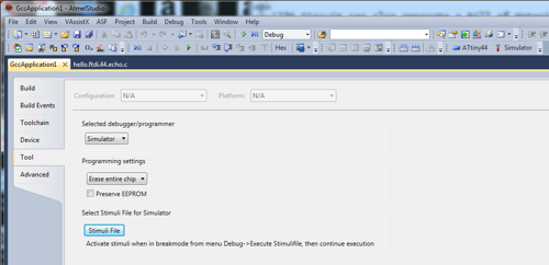
I tried to create a new Atmel Studio project using the ATtiny 44 but got stuck when it asked to define a stimuli file.
Files
- Eagle CAD schematic file for my FTDI echo board with pushbutton and LED.
- Eagle CAD board layout file for my FTDI echo board with pushbutton and LED.
- Diagram showing where components go on my FTDI echo board with pushbutton and LED - in png format
- My FTDI echo board with pushbutton and LED - Circuit board traces in png format
- My FTDI echo board with pushbutton and LED - Circuit board interior in png format. Note colors should be inverted.
- Example c program that I used for initially testing the my circuit board.
- Example make file that I used for initially testing the my circuit board..
Back to index