wk8 | embedded programming
Assignments :
- read a microcontroller data sheet
- program your board (the one with the button & LED) to do something
Download : .c and make file - button & blink
My notes :
21 march 2014 | introduction datasheet
We had general explanation from our tutor about the ATTINY44A datasheet.
( http://www.digikey.com/product-detail/en/ATTINY44A-SSU/ATTINY44A-SSU-ND/1914708
&
http://www.atmel.com/Images/doc8183.pdf )
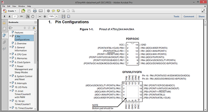
The text next to each pin is a description of the pins functions.
You can only use one function (of one pin) at the time.
Read & search (ctrl + F) in the datasheet,
if you want a extended description of each functions, and want to know how to apply it.
PB1 & PB0 : pins for a crystal, but they can also be used as regular pins (if no crystal is needed).
Reset pin :
- (in text) no line means it is as it says it is.
- line above it tells it is not reset, so ... ? needs 5V to work.
0 - 0V - Low - false
1 - 5V - High - true
Before setting the fuses, read the make file !
( http://academy.cba.mit.edu/classes/embedded_programming/hello.ftdi.44.echo.c.make
)
In the make file, there should be a line about programming fuses.
If your board does not have a crystal or a clock source, then check what fuses are being set.
24 march 2014 | Getting started
step 1 :
Start by downloading the
hello.ftdi.44.echo.interrupt.c
and the hello.ftdi.44.echo.interrupt.c.make file from the homework page.
There are 3 different files to choose from, I picked the 'interrupt' files.
(interrupt makes it possible that you can interrupt a loop on the board, and that's a good thing).
Save the file's in the development folder on your computer (c > dev > new folder).
step 2 :
In Command Prompt 'change directory' to the new folder, and enter:
make -f hello.ftdi.44.echo.interrupt.c.make
entering this 'make' command (without a specified option)
will compile the make file and create a hex file.
Make sure that you have checked the fuse settings (in the make file) before continuing.
step 3 :
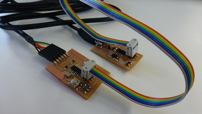
Connect the boards to each other and to the computer.
Make sure you don't connect upside down, because then nothing will happen.
(black wire = ground. And ground connects to ground!)
step 4 :
Execute the fuse and the make command.
(fuses command is a one time thing, because it sets the settings for the micro controller.)
(the make command means that it transfers the program you made to the board.)
C:\dev\hello-world-blink>make -f hello.ftdi.44.echo.interrupt.c.make program-usbtiny-fuses
C:\dev\hello-world-blink>make -f hello.ftdi.44.echo.interrupt.c.make program-usbtiny
step 5 :
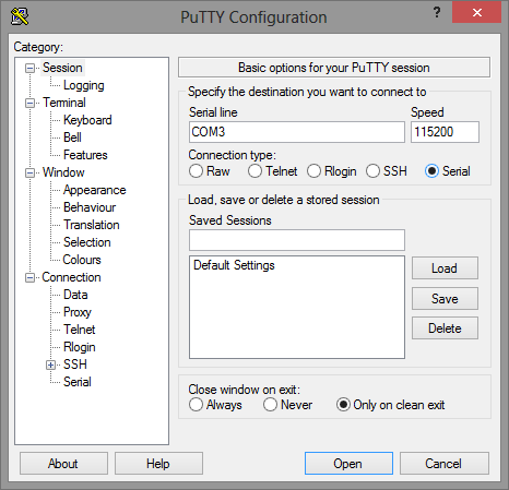
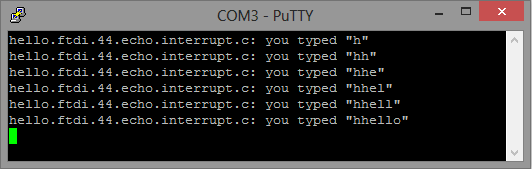
Start up the Putty program to see if the board works and give back an echo.

step 6 :
Let's add a first change in the hello.ftdi.44.echo.interrupt.c, like the 'carriage return'.
( http://www.asciitable.com ).
put_char(&serial_port, serial_pin_out, 13); //carrage return
After adding that to the code, repeat the make command, and check the result in Putty.
24 march 2014 | Blinking the LED in C
In the programming code you need to add 2 things.
The initializing of the pin (input, set or output) and in the main loop
you define what will happen (like delaying the blinking of the LED).
Check in the eagle schematic to see which pin is to connected to what.
LED1: PA7
LED2: PA3
LED3: PA1
Button: PB2
step 1 :
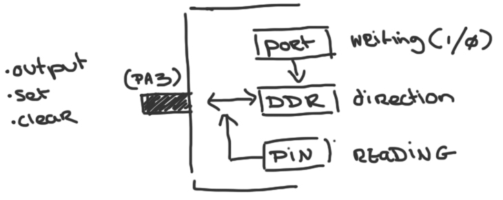
First add the initializing code > 'output (directions, pin)'.
output(DDRA, (1 << PA3));
-
What it says:
- the current will flow out from the micro controller (output).
- The data direction is A (DDRA)
- and pin 7 is turned on, one means 'on'. ( 1 << PA7)
- and always make sure to close all the '( )' and end with a ';'.
step 2 :
Adding something in the main loop like:
set(PORTA, (1 << PA3));
_delay_ms(500);
-
What it says:
- make make the current flow trough the led
- and the led blink gets delayed by 500 milliseconds.
To get the LED to blink in a pattern, add a clear (turn off LED) in the main loop as well.
clear(PORTA, (1 << PA7));
_delay_ms(500);
The main loop, loops around extremely quick, so adding a delay in after the each function will
help see that something is happening.
You can play around with the delay to get a different effect in blinking.
step 3 :
To add the button you can use a 'if & else' statement.
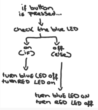
After a bit of trying my code looks like this:
// initialize LED pins
output(DDRA, (1 << PA7));
output(DDRA, (1 << PA2));
output(DDRA, (1 << PA3));
// initialize button
set(PORTB, (1 << PB2));
// main loop
while (1) {
// wait for button to be pressed
if (!pin_test(PINB,(1 << PB2))) { // checks if button is pressed
_delay_ms(10); // delay to prevent de-bounce effect in button to LED
if (pin_test(PORTA,(1 << PA7))) { // checks if blue light is on
clear(PORTA, (1 << PA7)); // clear blue light
set(PORTA, (1 << PA2)); // set red light
}
else {
set(PORTA, (1 << PA7)); // set blue light
clear(PORTA, (1 << PA2)); // clear red light
}
// checks if button is still pressed
while (!pin_test(PINB,(1 << PB2))) {
_delay_ms(1);
}
}
// keeps the green LED on
set(PORTA, (1 << PA3));
}
}