wk7 | computer-controlled machining
Assignments :
- make something big (shopbot)
Download : PDF & Vcarve - cabinet design files
My notes :
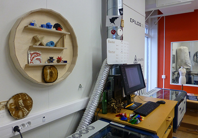
13 march 2014 | shopbot introduction
My tutor gave general explanation about how to work with the Shopbot & how to prep toolpath with V-Carve.
Tutorial shopbot :
http://fab.cba.mit.edu/content/tools/shopbot/index.html
14 march 2014 | shopbot design
My inspiration for this weeks assignment was a internet picture of a round cabinet.
The technique used for that design, for bending the wood, was wetting it and bending it slowly over a mold.
While doing some research I found a different approach using slots and plywood,
and decided this would make a nice experiment for learning to work with the shopbot.
First step is figuring out how many slots I would needs to bend the wood into a circle :
width circle 600 mm
thickness wood = 12.2 mm
diameter (outside + 2 x wood thickness)
10.7 x 2 = 21.4 mm + 600 mm = 621.4 mm x pi = 1952 mm
600 x pi = 1885 mm (inside of circle)
(outside circle - inside of circle ) 1952 - 1885 = 67 mm
tool shopbot = 3.175 mm (1/8 straight)
67 : 3.175 = 21 (slots for bending)
1952 : 21 = 93 mm (space between the slots)
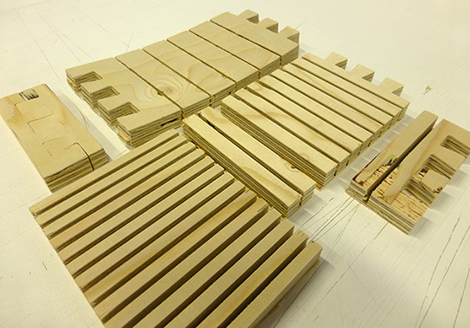
I made the design for the cabinet in illustrator, imported the pdf in V-carve,
edited the toolpath and cut out test pieces with the shopbot.
-
3 different sized test pieces result (varying with using more slots then calculated) :
- all 3 test bend, more slots means more bending.
- the press fit interlocks don't fit. note that the shopbot can cut outside corners sharp but not inside corners, so I need to take this in account while designing.
- And pay attention to the grain of the wood. For bending plywood instead of breaking it, the grain should follow the bend (so work with the grain not against it).
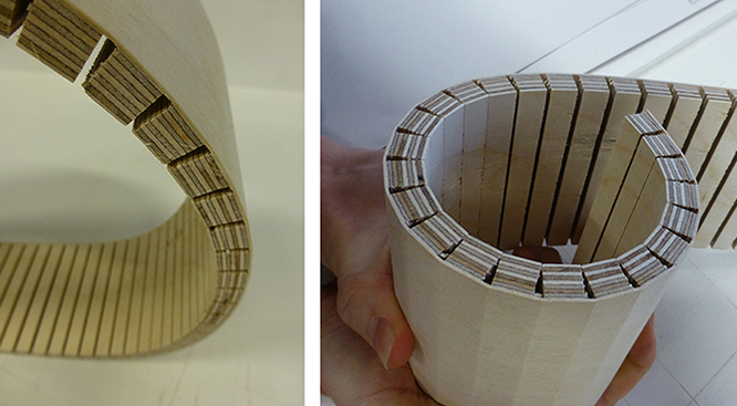
Next step is trying out a full circle (30 cm wide - using more slots then calculated).
I used a different (nicer) wood than I used for the test pieces.
With this piece I am able to bend it into a full circle, but because of the relative small size,
the wood will pressure itself into more a egg like shape then staying in a circular shape.
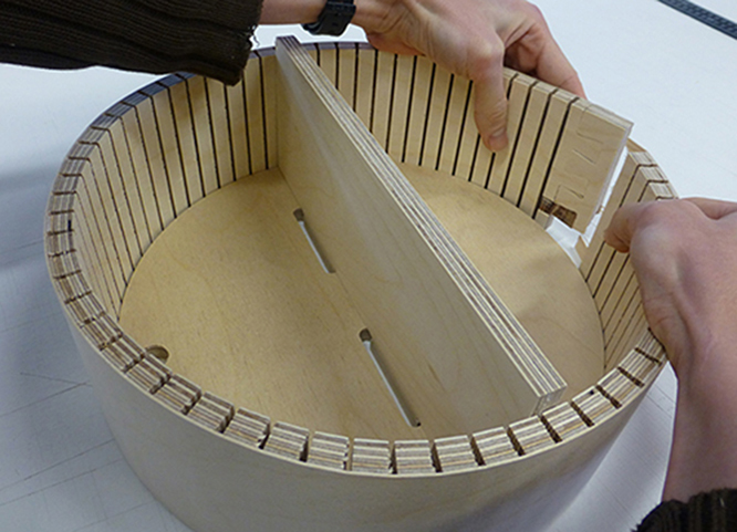
I tried to force the wood into a circle shape by cutting out a round back plate.
When putting the pieces together, I found out that I made a couple of thinking errors.
- I made a calculation mistake by making the back plate too big (we tried to force the back place in anyway, but it broke under the force).
- The back plate slots for the shelve had the wrong toolpath (it cut the outside line instead of inside).
- And the shelve itself is too deep (I forgot to subtract the thickness of the back plate).
- And for this version I choose to cut more grooves than I calculated beforehand.
Result is that it does bend nicely but now the wood doesn't close together on the inside.
17 march 2014 | V-carve
I edited the design a bit by scaling it up to 60cm wide.
About v-carve :
step 1 :
After importing the PDF design file in v-carve, the first step is to edit the document size.
Document size and thickness setting should correspond with the size of the wood.
And set the Z Zero to the bottom.
(it's a important choise, because you can control how deep the shopbot
will cut into the sacrificial layer)
step 2 :
In the toolset on the left pick the 'draw circle tool (create vectors).
Use this tool to draw circles aka screw holes (radius 10mm).
Now you can design where the screws should be plced ,
without colliding with the other milling paths of the shopbot.
Also the tool 'move selected objects' (transform objects) is also a useful tool.
This tool will allow you to move a selection from a relative or absolute (controlled) position.
step 3 :
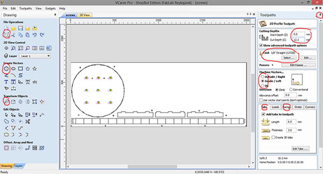
On the right of the screen there is a tab where you can create new toolpath's.
First select the lines in the design that will represent the new toolpath
(like all the drill holes)
and then select in the tab toolpaths > pocket toolpath (toolpath operations).
step 4 :
First fill in the cutting depth. To pre-cut where the screws should be,
the cutting depth should be around 3 mm deep.
And important to select the right tool. In my case I will cut the whole design (all the toolpath's)
with a 1/8 straight (13728) fluut.
Give the toolpath a proper name and click on calculate.
Then continue until the whole design has a appointed toolpath.
For regular cutting, use the profile toolpath.
The cut depth should be a little bit deeper then the actual wood is
(so my wood is 12.2 mm thick, and I set the cut depth to 12.3 mm).
In the machine vector option, be aware of the difference between outside/inside/on option.
It does make a difference in how the tool will follow the toolpath.
When working with wood, it is always wise to have tab edited into the toolpath.
This will prevent finished cutouts to go 'flying'. Small tabs of wood keep the cutout piece
connected to the rest.
Also editing in ramps are useful. Instead of driving/forcing the milling
head straight into the wood, it will be lead down a ramp.
When done, name the toolpath and click on calculate.
step 5 :
When done editing all the toolpaths, it is wise to take a small brake, come back,
check if all the settings are correct before exporting (button save toolpath).
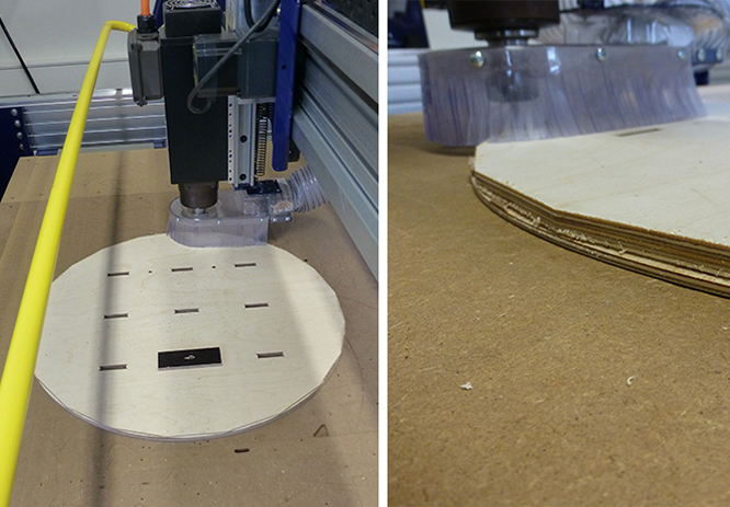
18 march 2014 | cutting all the parts
First set up the shopbot. (reset machine, change tool, plate of wood on the table,
set x/y/z axes, check rpm machine)
and also check then there is no more tools or other stuff lying around, that can potentially
interfere with the shopbot.
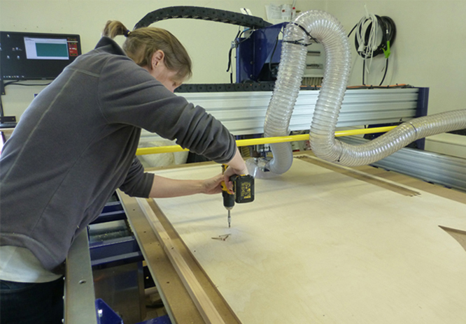
Load the drill holes toolpath first, turn on the spindel, when it sounds fine and is warmed up a bit, run the toolpath.
The machine will now prick holes for the screws, when machine is done, move the head out of the way and put the screws in place.
Then run the second file with the other toolpaths (slots, inside milling, outside milling).
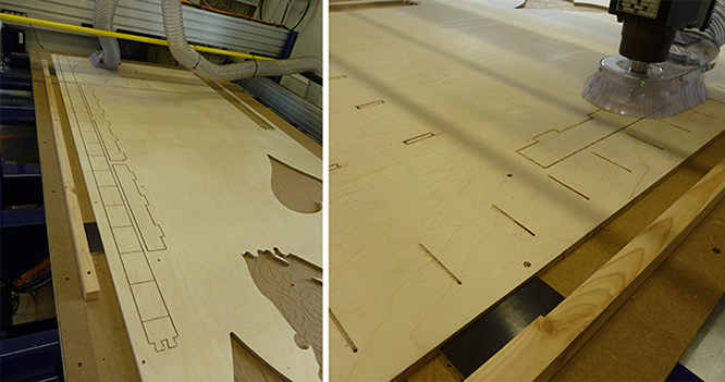
When done, move the milling head out of the way, unscrew the wood, and cut the tabs,
to take out the milled shapes.
Clean up the mess the shopbot created (milling dust) and sand down the splinters on the milled wood.
Because my milled circular shape is twice as big as the previous test,
I'm a bit afraid it will break if I bend it by force.
So this time I used water to soak the wood, and bended it slowly.
Then I let it dry, holding the circle in place with a piece of string.
Then soaking it again, and bending it to a full circle.
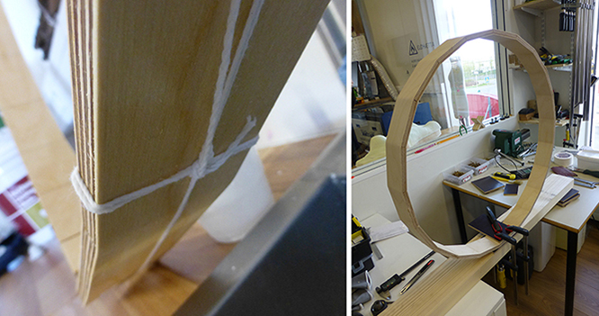
Now my (almost) hoop is dried, we can see that is new going to fit with the back pate.
Since my hoop is nit round enough, I'm afraid that if I will force it on my back plate,
it will brake.
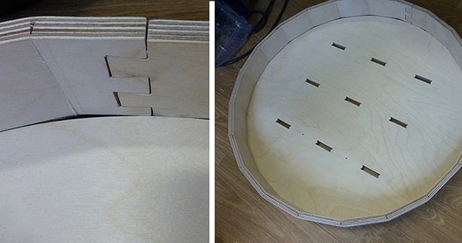
After consulting with my tutor we decided to edit the back plate to fit my hoop.
In v-carve I made a new file with only my cirkel and the 2 screw holes.
I replaced the circle with a 21 corners polygon shape.
After setting up the shopbot, I let the shopbot run the toolpath of the 2 screw holes,
to drill 2 holes in the sacrificial layer of the machine.
Then I screwed down my back plate in place, using those 2 holes.
This is a helpful trick to define the origin of the design,
without the need of using a new plate of wood.
Then I let the shopbot run the second file with the toolpath for the 21 polygon circle.
Now all fits together nicely.