wk10 | input devices
Assignment :
- measure something: add a sensor to a microcontroller board that you've designed and read it
Download : .c servo code, phyton code + eagle schematic & board
My notes :
3 april 2014 | step response sensor
With my final project already in mind I'm interested in making a step response touch sensor.
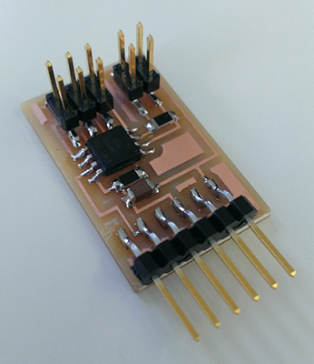
To get a better understanding of how the sensor works, I started with duplicating Neil's example board.
stepresponse :
http://academy.cba.mit.edu/classes/input_devices/index.html
hello.load.45.cad |
hello.load.45.c |
hello.load.45.make |
hello.load.45.py
After milling and stuffing the board I also made a touch pad of a piece of copper foil.
and on my laptop I installed Phyton (necessary to be able to see the data from the sensor).
On the board installed the program: make -f hello.load.45.make program-usbtiny
As a test I tried laying different materials over the touch pad to see how sensitive it is.
The sensor even responds when you 'touch' the pad from beneath the table.
But also the background noise is very visible. It increased when more people entered the same room.
4 april 2014 | designing my sensor
For this new design my tutor advised me to start with designing 2 touch pads, before making it more complicated.
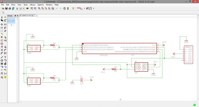
My schematic is the same as Neil's example board, but with a extra (4 pin) jumper.
I rearranged it a bit to make it fit.
PB3 and PB4 are now connected to the jumpers, and PB1 is used for the 'sense' of the jumper.
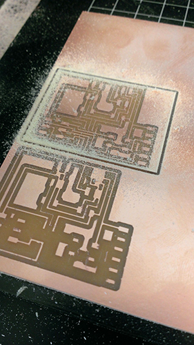
After routing comes the milling process. Which gave me some trouble this time.
I started by replacing the copper plate, because the leftovers were to small for my board design.
The first time I tried milling the traces the modela removed way too much copper.
The solution to this was simple, because my tutor noticed that I used the wrong (to big) milling bit.
Starting again (with the right milling bit this time) the traces looked ok, but the result was very 'hairy'.
Which is odd, because I used a new milling bit.
My tutor advised me that I could fix that later on with some steel wool.
So now I changed the milling bit's to the larger bit for cutting out the board.
Normally the modela runs 4 times along the same path before it is cut out. But this time it stopped after 3 times.
Tried again, but with the same result.
Turns out that I placed the milling bit to high in the machine which leaves no room for the machine to extend
further down for cutting the 4th path.
After placing the milling bit lower in the machine, the modela did what I expected.
And with steel wool I brushed away the 'hairyness'.
(later on, the same hairy problem appeared with another board.
But then it stopped doing that somewhere halfway of the board.
We concluded that 1 piece of the tape which holds the copper late in place wasn't good enough and caused
the plate to vibrate a bit.)
7 april 2014 | programing sensor in .C
To get a better understanding of what is happening in the .c file my tutor did some general explanation.
-
.c file:
- initialize output pins
- initialize ADC
- sends framing
- settle, charge, and wait 1
- initiate conversion
- wait for completion
- save result
- settle, discharge, and wait 1
- initiate conversion
- wait for completion
- save result
- send results
- wait 2: repeats top part but with a different timing.
- wait 3: repeats top part but with a different timing.
//main loop
//wait 1:
//does this for high and low
//does this for high and low
Neil's code is made for 1 sensor, and if I want to add a extra sensor I basically need to double everything
and tell the micro controller when to switch pin's (adc).
-
What I did was:
- move the framing code to the main loop.
- move the adc (mux) to the main loop.
- for the second sensor code I switch the adc to the other pin.
- copy and paste all the code from the first sensor (for the second sensor).
I learned that adding the framing to the main loop is necessary, because it is the data's recognizable starting point.
Since there are now have 2 sensors, you need a way to recognize when something ends/starts within the endless sting
of data.
How the adc (analog to digital converter) works and is applied can be found in the datasheet.
Here is also a list of how the mux is defined to which pin.
8 april 2014 | programing sensor in .py
Seeing python code for the first time actually gave me the feeling that I could understand what was happening there.
Getting this code to work for my second sensor, was a job of copying and renaming everything.
So filter1, filter2, filter3, gets copied and renamed too filter4, filter5 and filter6.
What did took some time, was figuring out how the coordinates were applied. Which number relates to which position.
Keeping the same coordinates as the first 3 sensors would result in not being able to fit everything on the screen.
So I messed around the 6 beams and the height of the window.
And later on added some different colors to the beams, to match my 2 flat cables connected to the touch pads.
#
canvas.coords('rect11',.2*WINDOW,.05*WINDOW,x1,.1*WINDOW)
canvas.coords('rect12',x1,.05*WINDOW,.9*WINDOW,.1*WINDOW)
#
canvas = Canvas(root, width=WINDOW, height=.75*WINDOW, background='white')
#
canvas.create_text(.1*WINDOW,.075*WINDOW,text="1",font=("Helvetica", 24),tags="text1",fill="#2c2c2c")
canvas.create_rectangle(.2*WINDOW,.05*WINDOW,.3*WINDOW,.1*WINDOW, tags='rect11', fill='#b00000')
canvas.create_rectangle(.3*WINDOW,.05*WINDOW,.9*WINDOW,.1*WINDOW, tags='rect12', fill='#eaf718')
And here's my end result: