FINAL PROJECT - GIMBAL
.jpg)
FINAL PROJECT - REFERENCES
link: SERVO MOTOR
link: MULTIWII
link: MULTIWII tutorial
FINAL PROJECT - DOWNLOADS
design files
INTRODUCTION
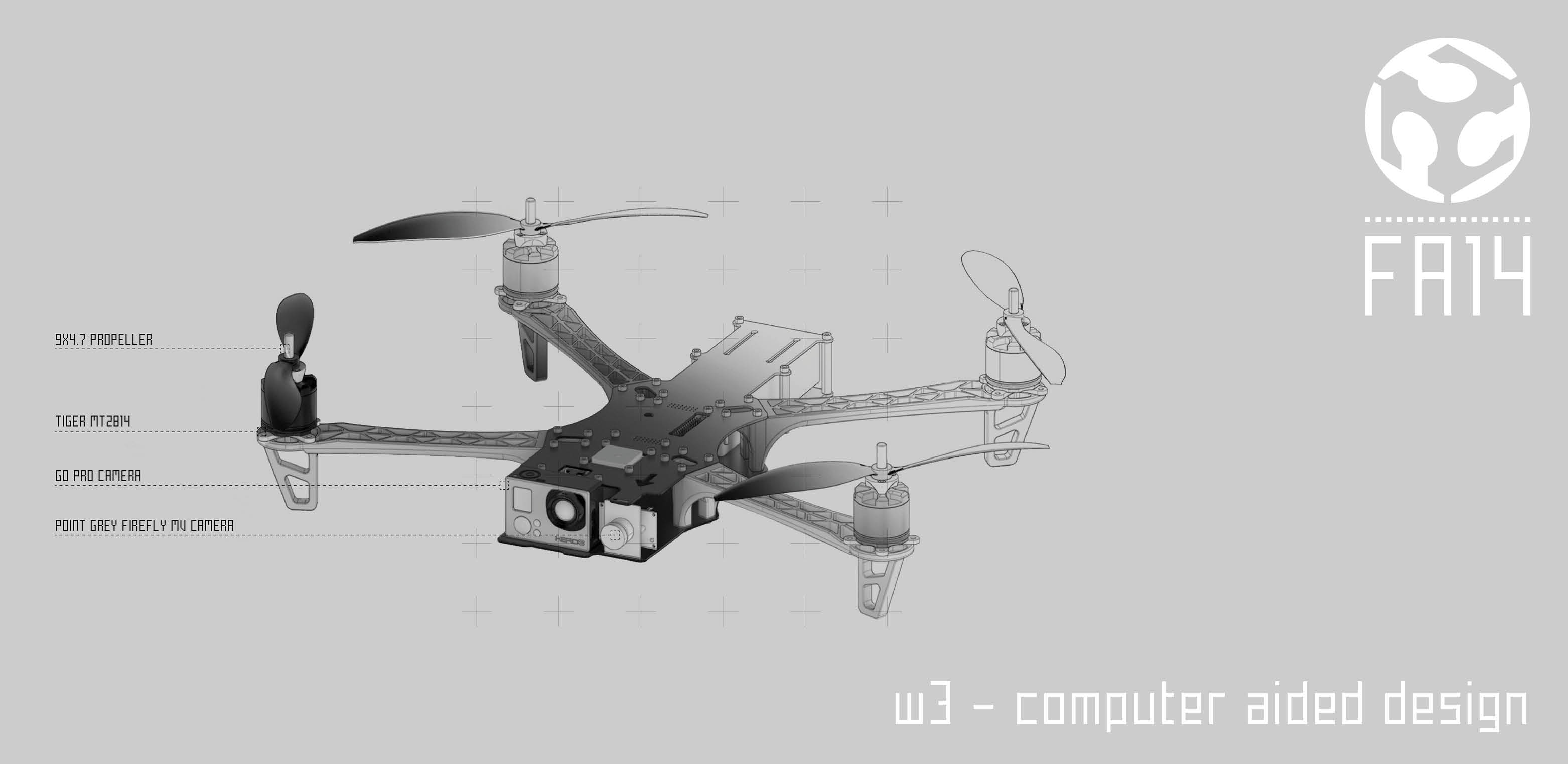
As mentioned in many parts of my FABACADEMY page my main goal since the beginning was to design and make fly a drone.
Doing such a project and getting into those kind of principles of electronics and fabrication was since the beginning an important step towards an experimentation on new tools for architects, designers, urban planners. As the Academy moved I decided, suggested by Neil, to join forces with another fab academy student – Chirag Rangholia - doing the same project of me.
Anyways to pass the fab academy each student is required to show his skills on every aspect learned during the fab academy. For this reason we decided to add another piece to our drone and present those components as separated even if part of the same project. In this section I’m going to focus on the making of the gimbal system.
DESIGN
The design phase was unexpectedly more difficult than what I imagined at the beginning.
I started adding unnecessary components as gears. It was a decision driven by the necessity of avoiding the installation of the servo motor on the same main axis of rotation. Is a good reason in fact if those two are on working on the same axis all stresses are directly translated to the servo.
To design the gears I relied on an existing definition made in grasshopper. Is very useful as it allows to change dimensions and several settings of the gears.
Anyways after several trials and changes of material, sizes, proportion of the gears and problems about the installation of the servos, I decided to move to a much more simple version.
In fact the servo used for the gimbal are very strong and can handle until 2.5 kg each.
The connection to the drone is designed with a system of two tubular bars connected and screw at the top over the main platform of the drone.
The design of the thread system was actually very fun and also interesting to fabricate. Again I used a grasshopper definition that is quite usefull to design bot threads and bolts.
.jpg)
.jpg)
FABRICATION
All the components of the gimbal have been 3d printed.
At the very beginning the ideas was to test all the components using the laser cut machine. And actually there is also a model about it.
Afterwards the decision was to move directy to the 3dprinter in the way to have more rigidity of all the pieces and avoid glue.
The initial polysurfaces model have been exported as a stl file and then converted in the makerbot open source software in a x3g file for the makerbot 3dprinting machine. The material used was always PLA but since several test were made the final result is a combination of parts extruded with different filaments.
The common thinking is that 3d printing is a very easy process: just put your file and print. The reality is not like this at all! It needs constant monitoring because the extruded sometimes loose heat or the filament get stuck and it can damage all the printing. But all the pieces were very small so it was affordable.
Of course it was necessary to adjust sizes, do bigger bolts and by the end some changes to improve the functionality of the gimbal would still be necessary. In fact as in the final design the gimbal is hung to the top bars with a U component that has a very small section. To avoid an inclination of all the system it would be necessary to increase this section or to print directly bars and U element all togheter. This is for sure one thing to do in future steps!
.jpg)
ELECTRONICS
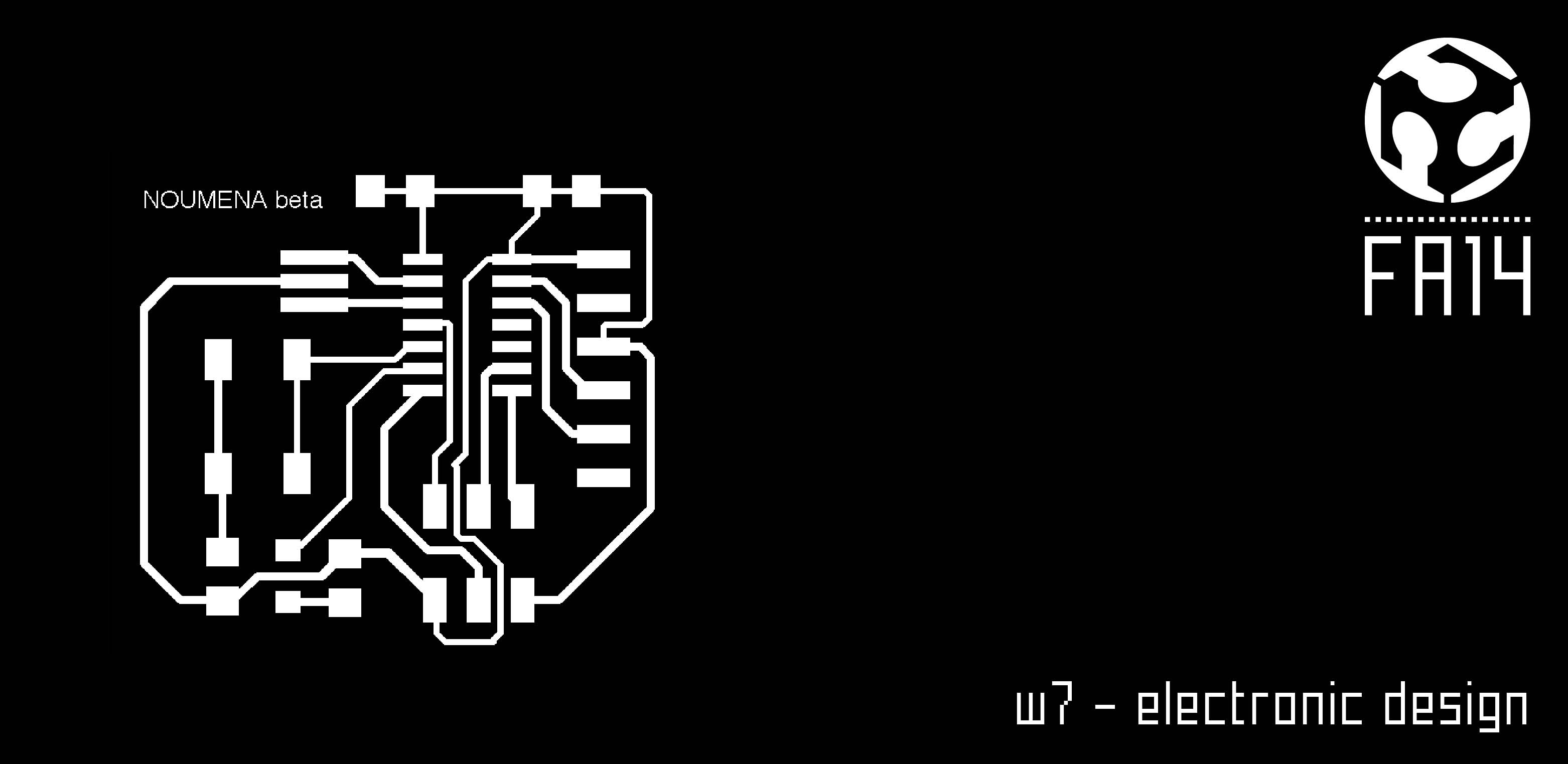
The electronic board that I designed under the tutoring of Guillem Camprodon and Luciano Betoldi is mainly an extension of the main board for the drone that my colleague Chirag Rangholia did.
The utility of this board is first to control all the brushless motors of the drone and the two servo motors of the gimbal. In order to do that it receive the 9V from the battery and provide this voltage directly to the brushless motors. Converting the 9V into 5V it also provide energy to the servo motors of the gimbal and to the main board itself. It is not a very complex board but actually is function is clear and usefull.
What can I change of this board? First the size. It’s too big. I did two of them and the second was is at least a little bit smaller because I basically offset all the external circuit since I do not need a rectangular shape.
Then I can also change the disposition of the components and would be very nice to have a sensor on it. The GPS would be one really nice to add.
Third point: Why can’t it be implemented directly to the main board? A drone is a flying machine. The smaller components are the better it is. Having two boards is fine for the academy issues but not at all for the optimization of spaces for the drone! The two boards have to be separated but also there is a distance range they can’t afford because of wiring. The best option for the future is one unique board for sure with integrated functionalities of this two that we have now.
.jpg)
PROGRAMMING
As for the electronics the code has to co-exist with the one of the drone. The main code for the drone is based on the multiwii code that is an opensource code available online.
The first configuration of MultiWii is done in the config.h file of the firmware source. With a programming IDE like Arduino or a simple text editor, you can change several options for your multicopter, flying wing or helicopter. This is done by adding or removing of the // in front of the #define parameters which comment or uncomment the line so it is included or not in the final firmware.
Once the code is changed the next step is to upload the firmware to the controller board with Arduino IDE or other means like an ISP programmer but the latest is more suited for experienced users that will know how to do it.
I found several links online that suggest to uncomment the //#gilmbal in order to activate it. Never work for me!
The mulitwii code has several tabs. The config.h is the main one. In our case the right setup was made by uncomenting the #define QUADX; then move to CAM STABILISATION and uncomment //#define SERVO_ TILT and copy paste this:
#define SERVO_TILT
#define TILT_PITCH_MIN 1020 //servo travel min, don't set it below 1020
#define TILT_PITCH_MAX 2000 //servo travel max, max value=2000
#define TILT_PITCH_MIDDLE 1500 //servo neutral value
#define TILT_PITCH_PROP -45 //servo proportional (tied to angle)
#define TILT_ROLL_MIN 1020
#define TILT_ROLL_MAX 2000
#define TILT_ROLL_MIDDLE 1500
#define TILT_ROLL_PROP -45
The pitch and roll proportion are the one very important to adjust according to the rotation of the drone. The best way to do it is uploading the file and really search for the right balance between them.
The pins for the servo on the main drone, that is actually using a atmega32u4 (Promicro) microcontroller, are A0 and A1 (#if defined(A0_A1_PIN_HEX)and is possible to find them in the Output.cpp tab.
That said the input of the board gimball is to receive informations from gyro and accelerometer from the main board, transfer those inputs to the shiedl and than directly to the servo that starts to rotate accordingly.
.jpg)
WRAP UP
As a final consideration I would say that I’m very happy with the goal achieved. The gimbal is moving quite good for the PITCH axis. It was working very fine also for the ROLL but something happen probably a problem of PINOUT on the main board and now is not reacting like before.
Next step:
• translate the code for an iphone app. We used an app for android developed by the guys of FLONE but it would be very nice to develop our own one.
• optimize the design of the drone according to stress test; dynamic fluid analysis; weight; number of arms (quadcopter, exacopter, octacopter…)
• optimize the design of the gimbal regarding the connection to the drone; it’s stability; the protection of the GOPRO camera.
• test more fabrication techniques. With the actual drone if a piece is lost probably most part have to be fabricated again. I would like to test a system made of modular components that can be interchanged quickly and economically.
I want to thanks Luciano Betoldi for the idea of the gimbal as the right implementation to the drone; Guillem Camprodon and Miguel Angel de Heras for the amazing help with the main and the secondary board of the drone; the team of FLONE made of Lot Amorós and Alex Oliver for the big number of suggestions and inspirations. Special thanks to my colleague Chirag Rangholia that worked very hard and provide a professional effort to solve each problem we faced.
Thank you fab academy!
.jpg)
.jpg)
.jpg)
Weekly Assignments