Resume of the lesson
After a quick introduction to electronics ( I really need to read the book "Electronic for the dummies"), we discover how to make a circuit in a practical way, using an EDA software like Eagle :- first drawing the schematic : this is the logical links between components
- and then creating the drawing of the circuit, linked to the previous schematic
Then we have an introduccion to the molding software, which provide a fully simulation of how will work a circuit.
Home Work
The job is to design the Hello Board using the EDA software Eagle, adding at least a Led and a switch, and make it. This is the original board :
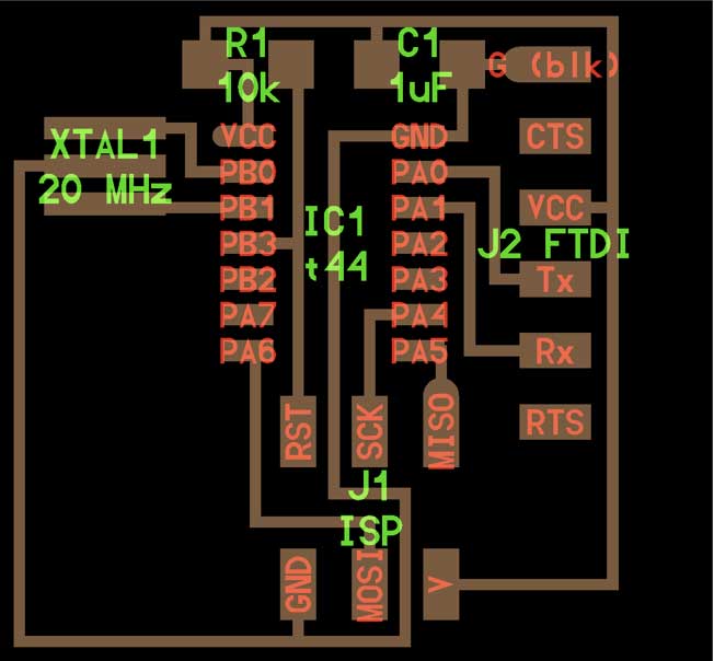
Designing the logical schematic was quit easy , after learning through tutorials how Eagle work. The problem came when I had to add a LED and a switch. At the begining we were a little bit afraid, but Luciano explain us that the Tiny44 circuit is at the end a microcontroller itself : some pin are use to power it ( the 2 on the top ) and all the other one are potencial I/O port , depending what you declare in the code.
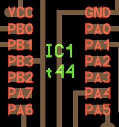
The only remaining doubt was which pin using . It seem there are 2 type of PIN : the PAx and the PBx, those last one only located on the left side. There are 4 free pins on the original Hello Board : the PB2 PA7 on the left, and PA2 PA3 on the right side.
Trying to understand what was the difference between the 2 type, I read the tecnical specs of the microcontroller ATTINY44A, made by Atmel ( pdf there : http://www.atmel.com/Images/doc8006.pdf), the only diference I was able to found is :
- Port B is a 4-bit bi-directional I/O port
- Port A is a 8-bit bi-directional I/O port
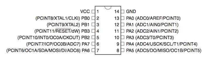
It appear it's only related to the acuracy of some sensors you can use (less definition in the 3 PBx ports) => so we can use both for adding the led, and the swich.
My objectiv is to made the smalest board posible => I've decided to put the news element in the left bottom side where there is plainty of space :
So I design a first schematic using Eagle, the most efectiv part of this software :
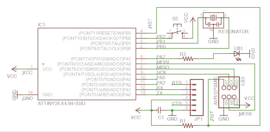
This is only when I start to think how I'll connect the new elements :
- the Led with his related resistor to the ground ( the pin will send the VCC signal to light up the Led)
- but for the switch what ? I don't really have knowledge in electronics but I realize that, if the swich is located in this area , he can only be connected to the ground, which doesn't make sens in my poor understanding.
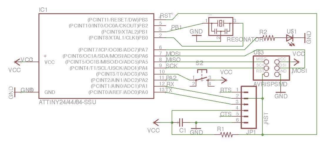
So I had to change my strategy , and redesign a new schematic, locating the switch on the rigth side, in order to be able to connect it to VCC. Learning : "always think before acting" :-(
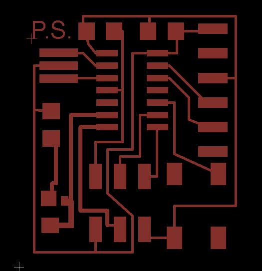
OK, then start the really painfull part of Eagle : drawing the board. It's really not a powerfull part of this software, and I understand why in the tutorial the guy said that he draw everything manually... Some example of the crazy results of the funccion "autorouter" and at the right side the manual draw done following the target to have the smallest board posible :
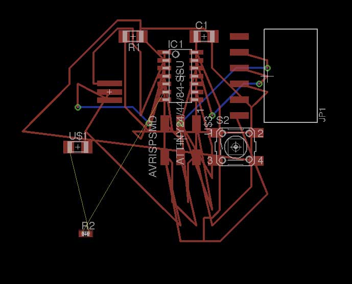
Because I was not sure about what would be the correct resistor linked to the led, I design 2 locations, with 2 different side :
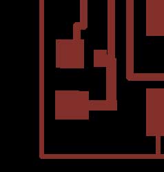
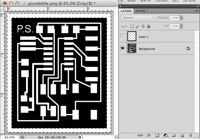
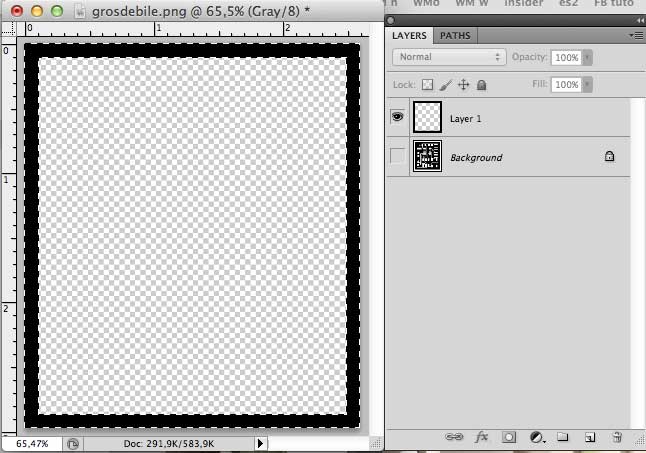
Then we export the circuit in a PNG format to photoshop, increase the canvas size 40 pixels in order to create the interior trace ( to cut the board correctly) using a new layer for it :
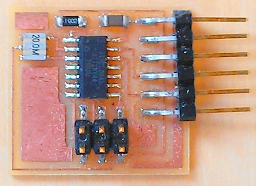
At the end, using what we've learnt 2 weeks ago , we make the board using the Roland milling machine :
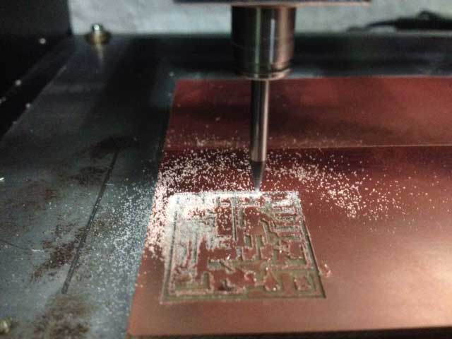
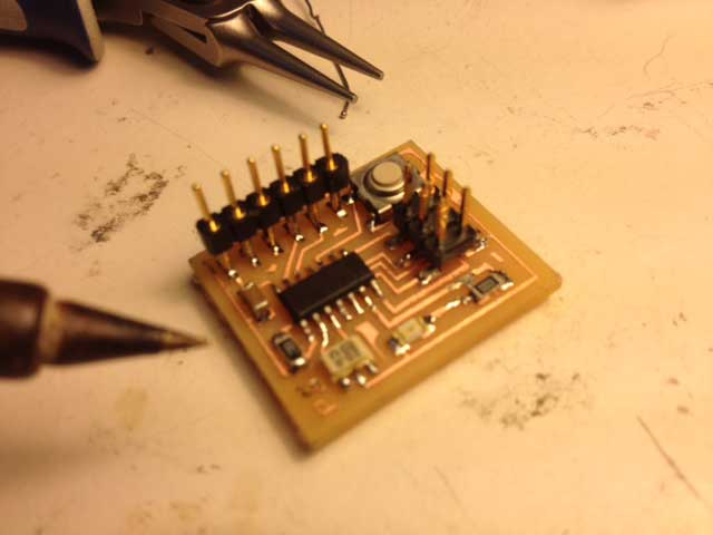
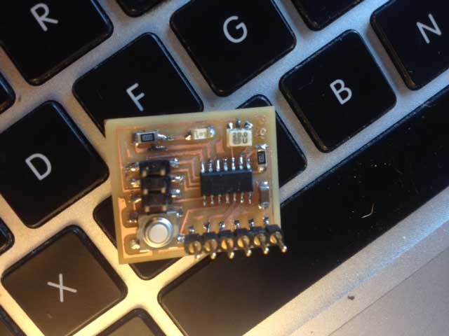
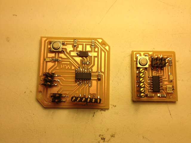
The result is a quit tiny board ! No idea if it will work , especially related to how I've conected the swich (I didn't use any resistor) : answer after the programing cours !