Schnyder - Embedded Programming: Getting the Button and LED
Working on the Board
This week I programmed my board so that the left LED blinked and
then changed the program so that the same LED lit when the button
was pressed. With a little bit of difficulty with the physical set
up to program the board, I completed the first program and the board
was behaving exactly as I wanted it too, but when I loaded the
second program I learned that I had some issues with my board that I
was not able to completely diagnose.
I used the Arduino software to program the board. I loaded the Arduino software and
the drivers for the ATtiny and the FabISP (the USBtinyISP
) onto my computer and plugged in my board and my FabISP to my
computer. I used the FTDI connector to provide power to my board.
The rightmost LED on my power is a pilot light that lights when the
board is properly powered. I had more trouble with the making a
connection between the FabISP and the board.
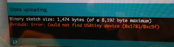
The first error message that I saw was that the Arduino could not
find the USBtiny device.
I tried an AVR mark II to program the board and that worked so we
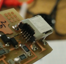
looked for a problem with the FabISP board. I double-checked the
cable connections and then looked at the USB header. One of the pins
had solder but looked like it was not attached to the underlying
trace, a bad solder joint. I had not tested that connection when I
had originally finished the FabISP.
I applied solder to any pin on the header that looked dubious and
went back to try to load the program. I connected the two boards
with the ribbon cable and tried to load a modified example sketch
that makes an LED blink. I got a different error, but one that did
not refer to a missing device.
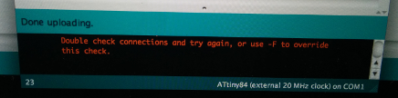
Since the FabISP was trying to program my custom board, I assumed
that the ribbon cable was plugged in to the board incorrectly. I
changed the orientation of one side of the cable and was able to
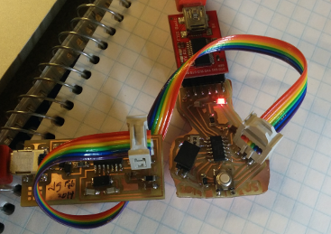
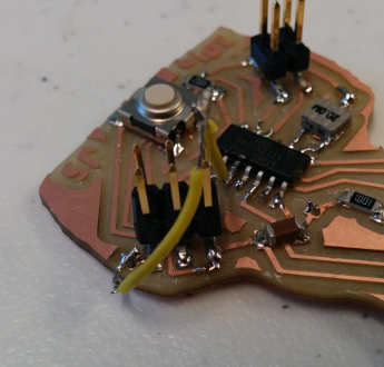
successfully load a sketch. In the future I should try to use keyed
headers or leave some sort of visual clue on the board (probably a
new version of the FabISP) to indicate a good connection. The
following picture shows the proper orientation for the ribbon cable
between the two boards.
Here is a picture of the second LED lit.

I moved on to try creating a sketch that would light the left LED
whenever the button was depressed. I found an example in the Arduino
software and modified it for my board. When I tested the button, I
found that the value on the button pin would float between High and
Low, so when I released the button, the LED stayed lit for a random
length of time and that if my hand came too close to the board, the
LED would occasionally light.
At this point I knew that I might have trouble with the board. I had
designed the button circuit to connect a pin between the ATtiny84
and power. What I needed on the pin was a pulldown resistor and the
ATtiny datasheet
only had internal pullup resistors. I thought about cutting the
power trace to the switch, but the trace itself powered a 4 pin
header and the resonator.
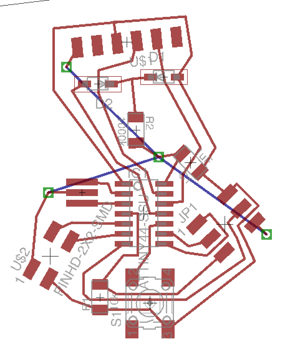
Instead I added a 10K pulldown resistor between the pin used to
monitor the button and ground (on the board, I used vias in certain
loctation to make the entire backside of the board ground). I added
the resistor and the button failed to work.
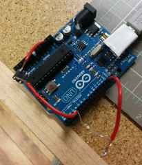
We used an Arduino board in the lab to test whether the circuit
worked. It did, the "button" (two wires to place into contact)
behaved as expected.
We went back the the board test and checked the voltage values of
the power and ground, the value of the 10K pulldown resistor and
that there was a connection between the pin and ground. The only
oddity to report, besides the pulldown circuit disabling the button,
is that the voltage drops by around 0.7 volts on either side of the
six-pin header. The trace between the six-pin header and the FTDI
header is 5 volts while the trace between the six-pin header and the
button is about 4.3 volts.
At this point I ran out of time to diagnose the issue. I redesigned
the board so that the button connects the pin to ground so that I
can take advantage of the internal pullup resistor to get cleaner
data values.