This week I assembled a FabISP, the hello.ISP. Overall things
went very well with the assembly--I had a working board without
having to do any rework. In my opinion that's mixed news, I didn't
get a chance to debug a board. I have no real experience with
soldering so I have to assume that I got lucky.
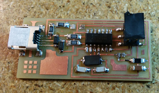
Starting with the milled board I started by populating the USB
header with a tack of solder on one of the feet (the solder iron
was set to 800). I then used the flux pen to apply flux to the
leads and corresponding traces. As carefully as I could, I applied
the solder to each lead, but I wound up with blobs that connected
the various leads. I used the copper braid to wick up the excess
solder by placing the braid over the excess solder and then
applying the iron to the braid. The solder joints on the traces
looked good so I bent the copper braid to keep the braid off of
the traces as much as possible. I used a multimeter to test the
connecting of each trace to its lead and also to check that other
leads weren't electrically connected. Once I verified each
connection, I added solder to the remaining feet of the header and
then resoldered the original tacked foot.
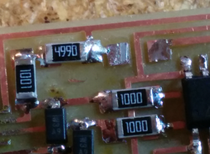
After attaching the USB header, I attached the components between
the USB header and the location of the Atmel chip. For the
resistors I used the common point on the corner as a tacking
point. The method I used to place components like these might not
be the best, but it worked. I put a bead of solder on the pad,
placed a component on the bead, applied light pressure with
tweezers, and remelted the solder. Then I would move on to the
other side.
After finishing all the components near the USB header, I placed
the Atmel chip where I soldered the leads one by one. Next I
placed the crystal, then the capacitors and other components,
followed by the solder bead. The last component I placed was the
other header.
Programming went fine.
Removing the 0 ohm resistor and the solder bead was relatively
simple. One of the resistor's pads looks like it remained on the
board.
To test my luck, I started a second version and will complete it throughout the course. For the next board, I will do the programming myself (using my original FabISP)