Electronics Design
Task:
redraw the echo hello-world board, add (at least) a button and LED (with current-limiting resistor) check the design rules, and make it. extra credit: simulate its operation
Description:
For this assignment I started with some tutorials on how to use the Eagle software. This tutorials can be found in the list at the bottom of the page. I used the help of our electronics guru Zaerc to explain me a few things. I created the helloBoard with an extra RGB led and TACT switch.
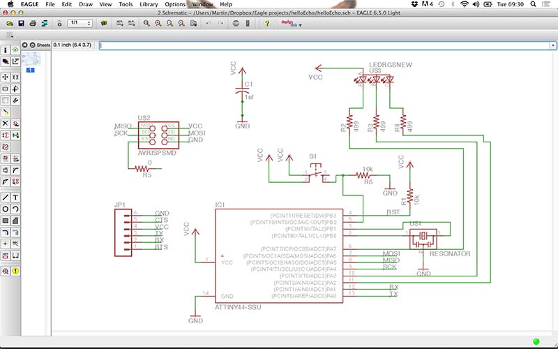
Scheme design:(image.1)
For my final project I have been working with some RGB LEDS, I want to be able to visualise different data with different colours. I decided to add an RGB led and switch to the helloBoard design. The extra parts needed for this are:
- PLCC 4 RGB LED
- 3x 499 Ω Resistors
- 1x 0 Ω resistor
- 1x 10K Ω resistor
- 1x TACT Switch
I had exactly four pins left on the ATTINY44, so I was able to connect the RGB LED and the switch. I connected the switch to pin number 5 and added a 10K resistor and ground(image.1). The RGB led is connect to pin numbers 6, 10 and 11 (image.1) between every pin to the RGB led I put a 499 Ω Resistor(image.1).
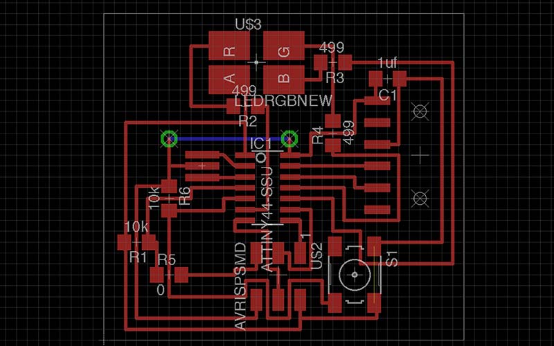
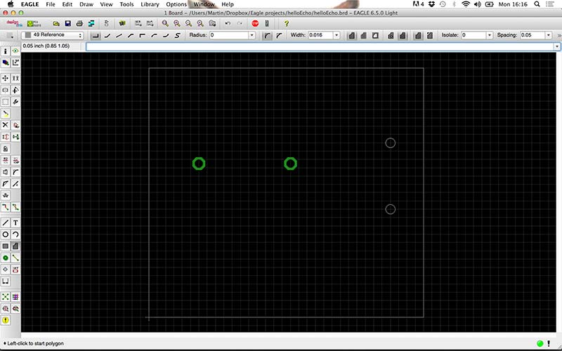
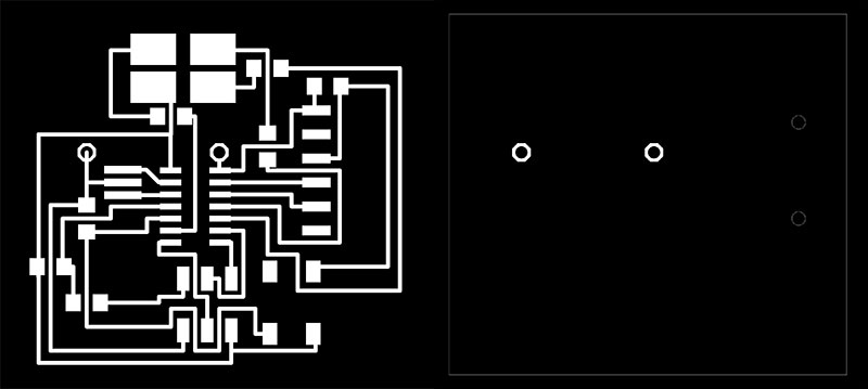
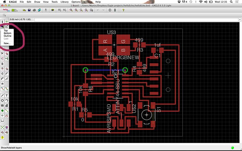
Board design:(image.2)
The board design I found the most difficult part, I was too stubborn for not wanting any cable bridges and 0 Ω resistors. I tried to figure out how to place everything without adding a bridge or a 0 Ω resistor. This took me a whole day until Dave and Zaerc convinced me you can not always do without cable bridges and 0 Ω resistor jumps. I added one cable bridge and one 0 Ω resistor bridge.
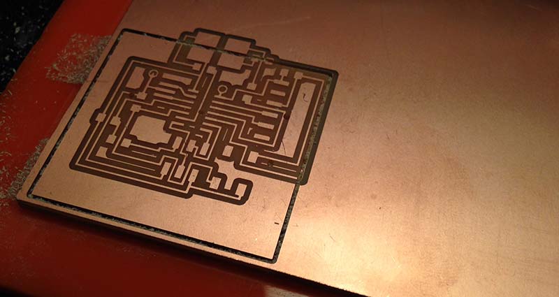
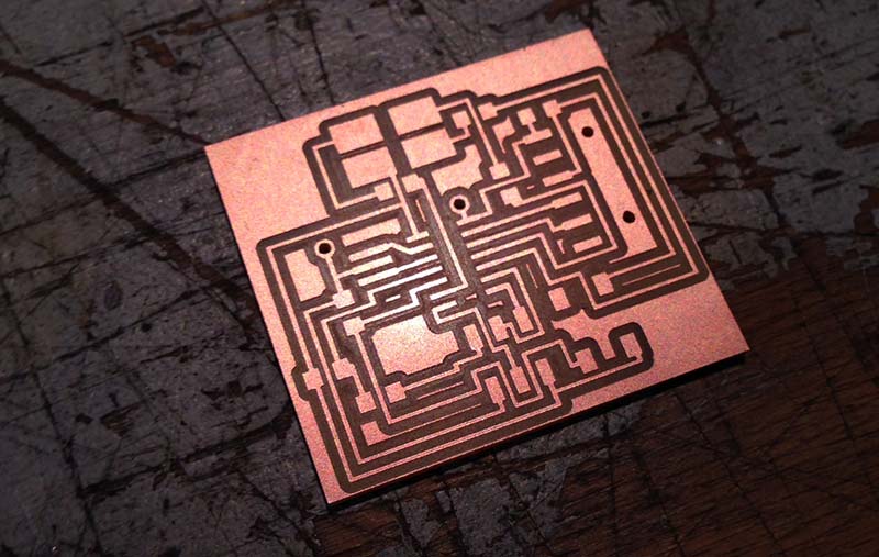
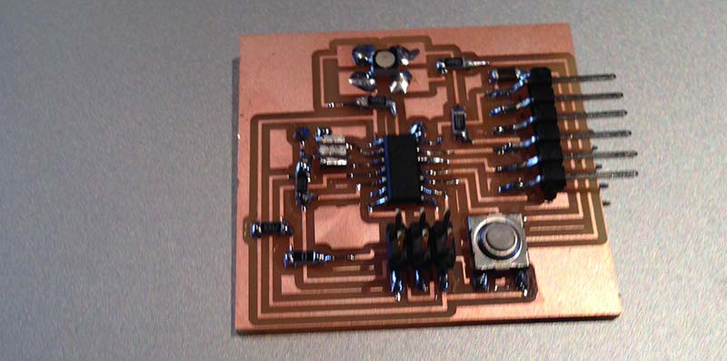
Milling:(image.6,7&8)
With the milling I feel quite comfortable with setting up everything because I already did this a couple of times. The first try went wrong because the settings where changed and both the milling traces & cut out board didn't start on the same X and Y position.(image.7) The second try worked.
Tip: Always make a picture from your settings before milling so you know what went wrong.
Assignment images:
Conclusion:
Forms follows function, because I was too busy thinking how my board would look like I took a lot of time in figuring out something that was impossible. I could not design the board without making a cable bridge. One thing I do want to learn is how to create a double sided circuit board so I can do this in a nicer way.
Eagle isn't the easiest program to learn but the tutorials from the bottom list helped a lot for the basics.