ASSIGNMENT
Design and build a wired &/or wireless network connecting at least two nodes.
WHAT I DID
- Asynchronous bus comunication.
- I2C bus comunication.
Since this top is new for me I wanted to do and understand how the less and most popular comunication ways work. I just reproduced the two Niel's examples: hello.bus.45 and hello.I2C.45.
ASYNCHRONOUS
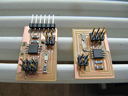
I designed the bridge board to use the device we had in laboratory:
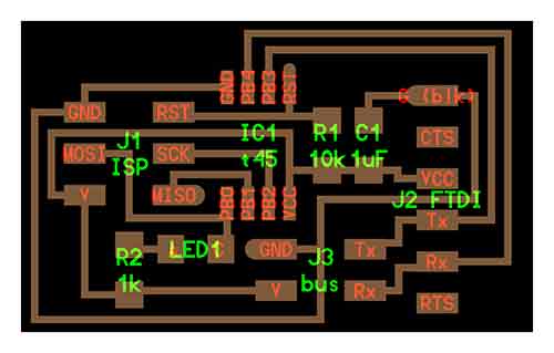
while the two nodes are the same:
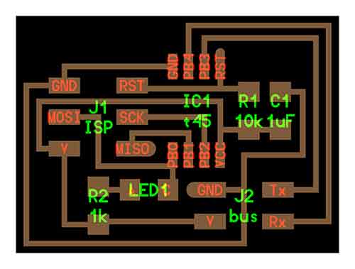
My boards are:
Following the tutorial /providence/tutorials/ I connected my bridge through FabISP and installed the hello.bus.45.c. I repeated the same process for the nodes changing the command: #define node_id '1' and #define node_id '2'. I could make the two nodes answering but the bridge wasn't. I had to change:
#define bit_delay_time 100 // bit delay for 9600 with overhead
up to 104. It worked!!
I2C COMUNICATION
It was not easy at all. I didn't have any ideas how the I2C comunication work and I needed to understand how it works, I had to understand what it is about. I think that the following article is well explained and http://www.hobbytronics.co.uk/arduino-external-eeprom and it includes the main informations that Dave gave to me during our 'I2C...what is it?' educational session.
For a time matter I couldn't try this protocol on ATTiny and I only tested it on Arduino Uno board, using a EEPROM memory, 24C65.
I defined the address trhough hardware (shorting the pin A0, A1, A2) to 0x50 or 80 (pink wires), I connected the comunications pin SCL to pin A5 and SDA to A4 (purple and yellow wires) both 10k resistor pulled-up, http://arduino.cc/en/reference/wire. Supply could be both, 3.3V and 5V. Based on Wire.h library and online examples I could write and read back from the EEPROM to a definite address. My code is:
#include <Wire.h>
#define disk1 0x50 //Address of 24C256 eeprom chip
void setup(void)
{
Serial.begin(9600); //open the serial comunication
Wire.begin(); // Initiate the Wire library and join the I2C bus as a master or slave.
}
In void loop I call the functions writeEEPROM and readEEPROM that I define below.
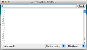
void loop(){
unsigned int address = 0;
writeEEPROM(disk1, address, 123);
Serial.println(readEEPROM(disk1, address), DEC);
}
"Lets first start off with the writeEEPROM function.This function takes three arguments, the device address(the disk1 variable), the memory address on the eeprom and the byte of data you want to write. The first argument is the address of the device you want to write to, in our case we only have one device(disk1) so we pass this on. The next argument is the address on the eeprom you want to write to and as stated above can be between 0 and 32,767. Finally we have to pass along the byte we want to store. So, writeEEPROM(disk1, address, 123) is going to write the decimal 123 to "address"(which is 0) on disk1(0×50). Lets jump into the actual writeEEPROM function to learn what it does. We first call the Wire.beginTransmission function which sends the deviceaddress to let the chip know we want to communicate with it. Next we have to send the address on the eeprom we want to write to. Since our eeprom chip has 32,000 address locations we are using two bytes(16 bits) to store the address but we can only send one byte at a time so we have to split it up. The first send function takes the eeaddress and shifts the bits to the right by eight which moves the higher end of the 16 bit address down to the lower eight bits. Next we do a bitwise AND to get just the last eight bits." From arduino-external-eeprom.
void writeEEPROM(int deviceaddress, unsigned int eeaddress, byte data )
{
Wire.beginTransmission(deviceaddress);
Wire.write((int)(eeaddress >> 8)); // MSB
Wire.write((int)(eeaddress & 0xFF)); // LSB
Wire.write(data);
Wire.endTransmission();
delay(5);
}
"The readEEPROM accepts two arguments and returns on byte(the data). The arguments it accepts are the same first two arguments the write function, the device address and the address on the eeprom to read from. First we declare a variable to store the byte we're going to retrieve. Next we start off just like we did with the write function by starting the process with beginTransmission and then we send the address we want to access; this works exactly the same way as the write function. Continuing on we end the the transmission and we've now set the 24LC256 with the address we're interested in so now we just have to request and read the data. The next function requestFrom() sends the command to that chip to start sending the data at the address we set above. The second argument is how many bytes(starting at this address) to send back; we're only requesting one. Finally we check to see if there is data available on the I²C bus and if there is we read it into the rdata variable. We return the byte of data." From arduino-external-eeprom.
byte readEEPROM(int deviceaddress, unsigned int eeaddress )
{
byte rdata = 0xFF;
Wire.beginTransmission(deviceaddress);
Wire.write((int)(eeaddress >> 8)); // MSB
Wire.write((int)(eeaddress & 0xFF)); // LSB
Wire.endTransmission();
Wire.requestFrom(deviceaddress,1);
if (Wire.available()) rdata = Wire.read();
return rdata;
}
The output on the serial monitor is:
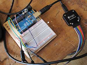
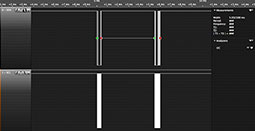
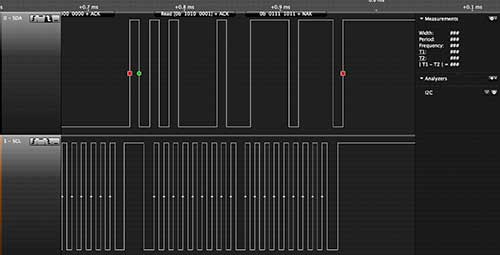
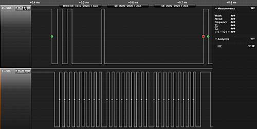
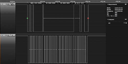
Ok, I didn't write the code by myself but I was happy I could manage and overly understand it. To see the real signals moving between the microcontroller and the memory I could use a very inSo I was curious to see the real signals I had the chance to use a very interested tool, https://www.saleae.com. I could trigger the analys on a change of state of the two signals and save the data to recall whenever you need the analysis.
Tools
Software: Eagle, Logic.
Machine: Rolan Modela DMX-20, Saleae Logic Analyzer.