


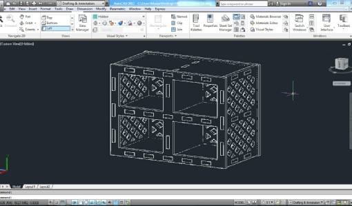
For this assignment I am going to make a shoe rack. First I need to design it using a CAD application. I drew the components and made a 3D digital model of the product to check and see if the parts fit together and get an idea about how the final product is going to look like. If something is wrong I can fix it. As it can be seen in the front picture the parts are designed as a snap-
Next I need to prepare the needed parts for cutting. Since there is no ‘shopbot’ available in our lab, we need to go to the ‘Maklab’ for this assignment. At the beginning we were told that the only available material is 4 mm plywood sheets. But later we realized that we only could work with 18 mm plywood sheets. Therefore we had to make slight changes to the initial designs to fit the new profile.
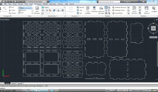
After preparing the DWG files we needed to save them as DXF as ‘Vcarve’, the application we are going to use to create the toolpath accepts this file format. Using the ‘Vcarve professional’ allowed us to join the vectors together so we have one unified vector which will make the cutting process better organized. Then we needed to prioritise the progress. For example smaller pieces inside the bigger pieces (such as the joint holes) need to be cut first and bigger parts of the outside (such as the piece boundary) need to be cut later. The professional version of the app also enables us to ‘fillet’ the corners to match the cutter’s profile. These fillets are especially essential in the joints. The smallest available cutter had 6.3 mm diameter thus we needed to organize everything based on this parameter. The other ability provided by the professional version is the ‘nest’ command. Using this command we can define a margin distance from the edge of the billet. It is necessary when we use screws or clamps around the plywood sheet to stick it to the machine’s bed. By this command we also can organize the distance between the pieces based on the cutter’s diameter. For long cuts such as the outer cuts we need to add ‘tabs’ and their numbers are related to the length of the cut. Tabs are small connection between the piece and billet which causes the piece to stay in its original position during the lengthy cuts. At last we need to save the toolpaths in ‘NC’ format. For that we need to choose a processor which is dependent to the type of machine we use. We can also save the file in ‘crv’ format which later can be reused in Vcarve.
Next step is to setup the machine. Here is our story with the machine in the Maklab: as I mentioned before at first we were told to design our product to be cut on a 4 mm plywood sheet. During the first two attempts the operator managed to break the two 3 mm cutters the had available. We did not know the reason why the cutters kept breaking. We modified our designs to cut on 18 mm sheet and they used 6.3 mm cutters but this time it caused fire! In the end we realized that the cutter was spinning in the wrong direction. This was due to the fact that the Maklab was recently moved to their new place and the machine parts were separated and reassembled in the new place but apparently two wires were connected the other way around and caused this problem. We needed to wait for a few days until the machine got fixed.
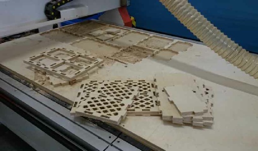
The second time we went there and eventually managed to cut my project. The problem this time was that the pieces were scaled down to 57% of their original size! It is strange because z axis was cut as planned but the X and Y axis were shrunk therefore joints could not fit together. We realized that the problem was caused because of choosing the wrong processor in making the NC file. As it can be seen in the picture, parts which were assembled in a full sheet of plywood (2.4 X 1.2 m) were cut in only half of the sheet.
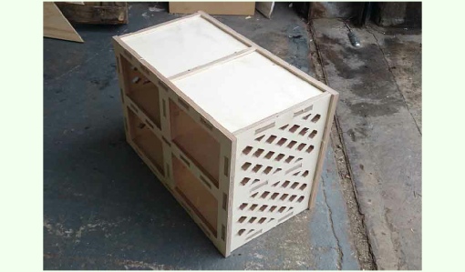
After all of those problems I managed to do it on the third attempt. Pieces are ready for assembly. I did not even need a hammer. All fit together perfectly. The only problem is that since it supposed to be cut on a 4 mm plywood and ended up on a 18 mm sheet, the end product was too heavy and looked over structured. Apart from that it is perfect. I guess now it has a function added to it. Apart from being just a shoe rack people can also sit on it and tie their shoes!
By clicking on this link you can access the CAD file.