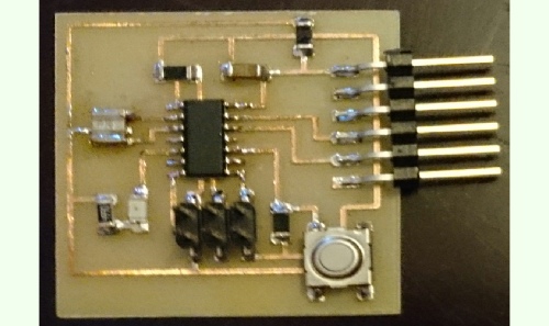


For this week, the task is to modify and redesign the PCB layout which is shown in the front picture. We have to add at least one LED and a switch to the board.
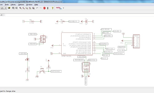
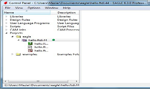
To design the board I used the ‘EAGLE’ application. There is a free version available for download at their website (http://www.cadsoftusa.com) which is limited compared to the full version but is adequate for the purpose of this project. After installing the software I copied the ‘fab library to the eagle folder in order to use its components in my design. we need to create a new project from the ‘File’ menu. After that we need to create a schematic by right click on the name of the new project we make. By opening the schematic page we can start designing.
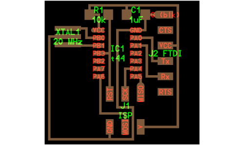
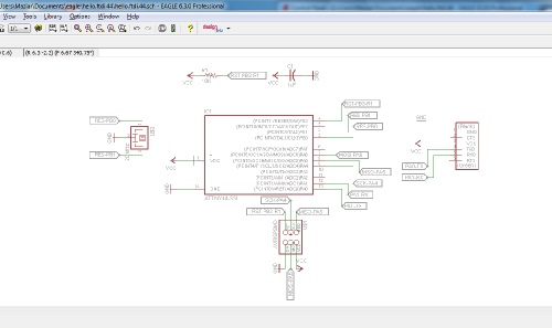
First I reproduced a schematic version of the original PCB
Then I add the additional components which are the LED and the switch. We need a pull-
By clicking on this link you can access the schematic file.
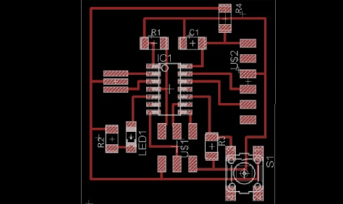
First I tried to cut the board using the traces that are shown in the front picture. After a few unsuccessful tries I realized that the only 0.2mm cutter in our lab has become blunt causing the failures in cutting very small and compact areas (especially in the area between the two row of the micro controller’s pins). I tried the 0.3mm cutter and it was a failure again. I tried to narrow the traces using thinner route thickness but the cutter pull off the small routes. Therefore I had to change the design to create more space in the compact areas.
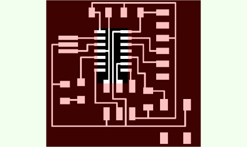
I moved some routes and had to add the ‘R4’ which is a 0 ohm resistor as jumper.
By clicking on this link you can access the board file.
In the end I saved the traces as PNG and cut the board with ‘Modela’, sand it, washed it with water and soap and stuffed it with the intended components. It is important to note that direction is important when soldering the micro controller, switch and the LED.