


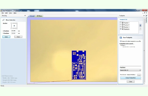
I believe that for a person like me who does not know much about the electronics and making electronic boards, using the ‘fab module’ to mill the board would be much easier and straightforward as it could get the ‘PNG’ file and create tool path from it and transfer the data to the milling machine. Yet, because there was no suitable cable available in our workshop we had to use other software. First we imported the PNG file in the ‘Serif Draw Plus’ and saved it as PDF which could contain vectors in it. Then we imported the PDF file in ‘Vcarve’ and created the machining tool-
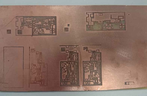
Generally working with the ‘Modela’ appears to be much harder compared to other two machines that we used so far. We have to manually set the Z axis each time we need to use the machine. This makes the whole process prone to be vulnerable by human mistakes. Also because of the fact that the machine will cut so little deep into the material in electronics production, slight vertical movements of the material sheet or the cutting bed may cause failure. In some cases the tool-
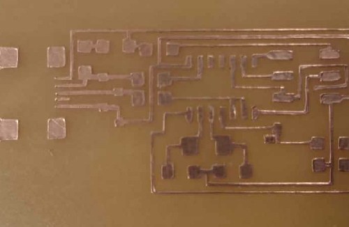
A collection of mistakes and failures can be seen in the picture!
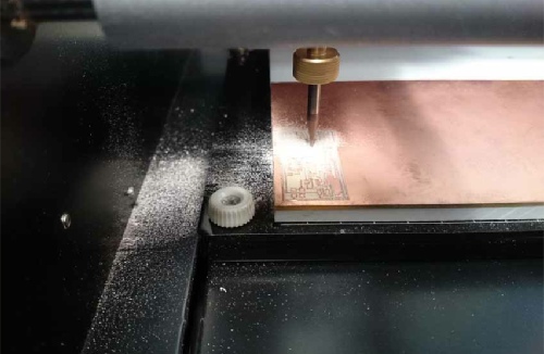
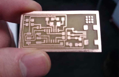
Finally the traces are being milled on the board. It is useful to remove the swarfs once in a while by a small brush. Milling the traces took around 80 minutes. The settings are as follow:
Diameter: 0.2 mm
Pass depth: 0.2 mm
Stepover: 0.08 40%
Spindle: 10000
Feed rate: 2.0 m/sec
Plunge rate: 1.0 msec
Cut depth: 0.15 mm
Start: 0.0
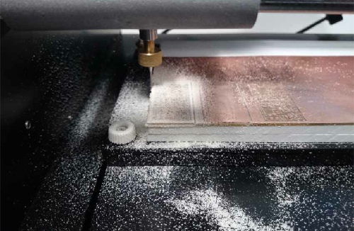
Then used a thicker head to cut out the circuit. It is essential to have a support layer underneath the material board to support the bed against the accidental milling. This process took almost 15 minutes
Settings are as follow:
Diameter: 1.0 mm
Pass depth: 0.2 mm
Stepover: 0.04 40%
Spindle: 10000 r.p.m
Feed rate: 2.0 m/sec
Plunge rate: 0.5 m/sec
Cut depth: 2.5 mm (the thickness of our material sheet)
Start: 0.0
After the milling is finished we need to polish the circuit using a very fine sand paper to remove the rough edges and oxides. The picture shows the circuit after sanding and washing with water and soap.
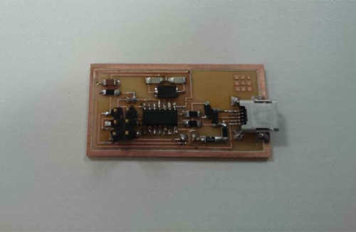
It is soldering time. As I mentioned before, it is best to remove any oxide from the surface. This will allow better flow of solder. It is useful to use chisel tip iron (for better heat transfer) and leaded solder (less than 0.5 mm thick) with flux. They make the process much easier. I used a magnifying glass and it helped me a lot since the components were very small. 350 °C appears to be the right temperature for soldering. It is very easy to create a short circuit thus inspecting by a magnifying glass is vital.
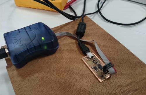
Next is the programming. First we need to connect the programmer to the board. In order to provide power for the board we need to connect it to a computer using a USB cable. The green light on the device turns on. Then downloaded the fab firmware and followed the instructions to program the chip. The programming was done without any errors. Afterwards we need to remove the jumpers.

I also tried to cut the traces by vinyl cutter and stuck it over a surface. Firstly, it is very hard to cut such a circuit with very narrow lines as narrow lines may move from their places and ruin the whole circuit. It is very fast. It only takes 10 seconds to cut; sticking and removing extra parts only takes couple of minutes. But working with It is very tough as the plates easily come off the surface when heated by the soldering iron.